
How to align the ITM heads to be in tolerance for accurate tool measurements.
Scan to View on Mobile Device

ITM Calibration and Alignment Video can be found here for direction to show how to do the beam align process.
Read Enire Document Before Making Adjustments
ITM Beam and Tool axis definition and tolerance:
Beam Axis is how parallel the beam is with the axis. Tolerance is +/- 0.010 from zero
Tool axis is how parallel the beam is with the spindle. Tolerance is +/- 0.005 from zero
Correcting Beam and Tool axis issues
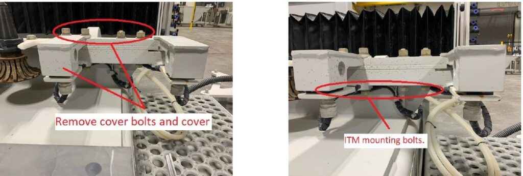
1. Remove ITM cover nuts and remove cover and set aside.
2. Slightly Loosen the ITM mounting bolts on the bottom of the ITM bracket.
Correcting tool axis issues
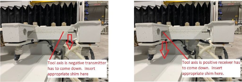
1. Using images below shim between machine frame and ITM assembly to correct tool axis issues
2. When Movement is complete snug up ITM mounting bolts
3. Run Beam Align in ITM screen to see if issue is fixed. If not repeat the steps above until issues is resolved.
Correcting beam axis issues
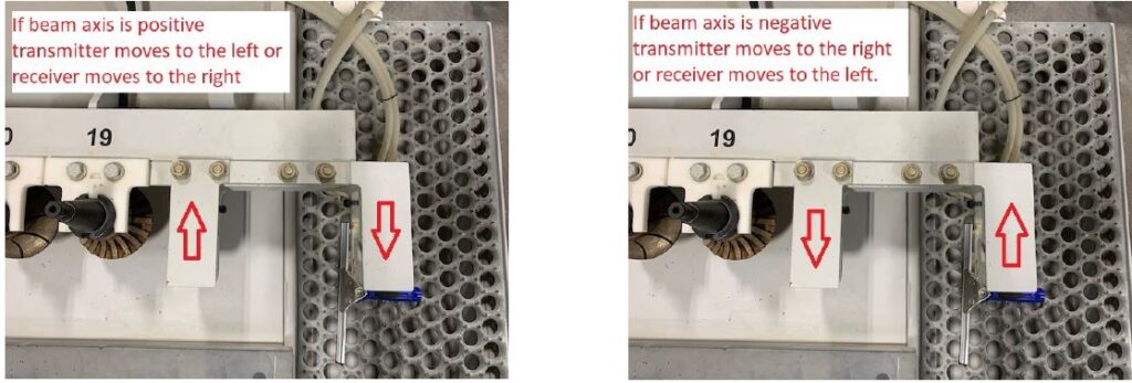
1. Using images below twist ITM assembly to correct for beam axis out of tolerance.
2. When movement is complete snug up ITM mounting bolts.
3. Run Beam Align in ITM screen to see if issue is fixed. If not repeat steps above until issue is resolved.