
- This procedure will take about four hours and at times will require at least one additional worker. Installing the travel extension kit consists of the following tasks.
- Mechanical Install Tasks
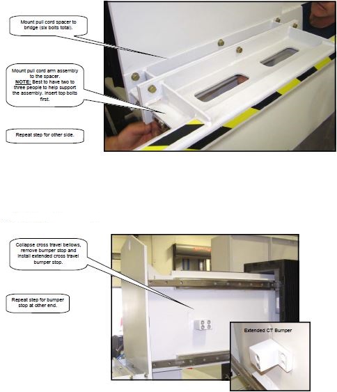
- Pull Cord Arm Spacer
- Cross Travel Bumper Stop
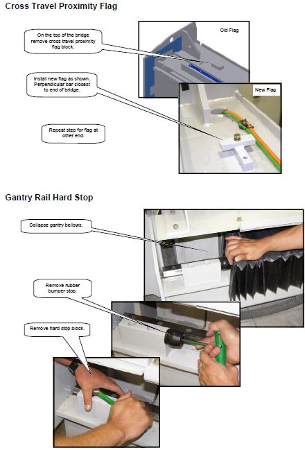
- Cross Travel Proximity Flag
- Gantry Rail Hard Stop
- Gantry Travel Flag
- Setup Tasks
- Reference Machine
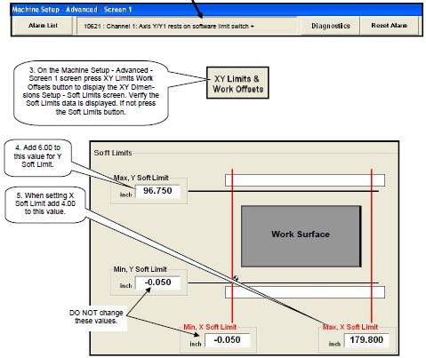
- Set Soft Limits
- Set Table Offset
- Set Blade-to-Nozzle Offset (calibration square)
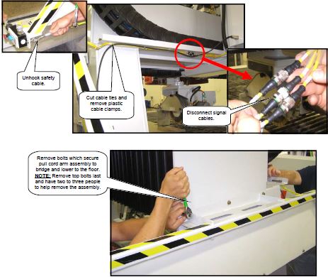
Installing the Pull Cord Arm Spacer Installation
Adding in new Flags and Hard stops
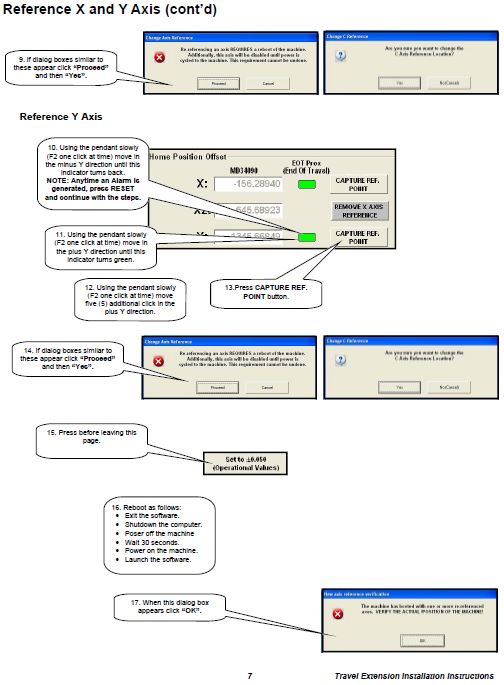
Referencing X and Y Axes after bolting on new hard stops
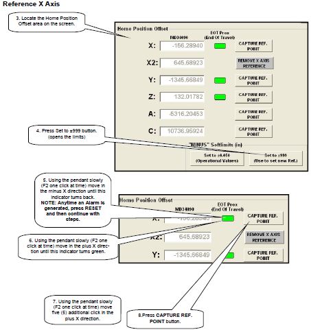
- Reference X and Y AXIS. This procedure list the steps to set both the X and Y Zero reference point and which limit (hard or soft) stops the machine and how to change or re-set the maximum X and Y soft limits.
- Using the Pendant move to the minus X and minus Y soft limits. Use the following steps to open > Machine Setup > Advanced Screen 1 Screen.
- From the Main Menu press SETUP Button
- On the Setup Screen press Advance Setup Button.
- Using the on screen keyboard enter the password: SUNRISE
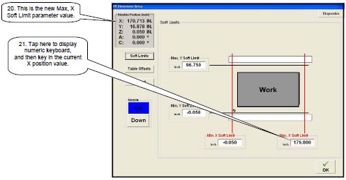
Changing the soft limits
- Reference X and Y AXIS. This procedure list the steps to set both the X and Y Zero reference point and which limit (hard or soft) stops the machine and how to change or re-set the maximum X and Y soft limits.
- Using the Pendant move to the minus X and minus Y soft limits. Use the following steps to open > Machine Setup > Advanced Screen, 1 Screen.
- From the Main Menu press SETUP Button
- On the Setup Screen press Advance Setup Button.
- Using the on screen keyboard enter the password: SUNRISE
Setting Soft Limit – Single Table Model (cont’d)
- On the XY Dimensions Setup – Soft Limits screen, press the OK button to display the Machine Setup – Advanced – Screen 1 screen again.
NOTE: Completely read the next step before attempting to the move to the hard limit. - On the pendant depress activation button, select Y axis, F2 distance and then rotate the hand wheel slowly (one click at a time) in the positive direction until a hard limit alarm is displayed in Machine Setup’s message display window. PAUSE 1 to 2 seconds between each click.
- Press Reset Alarm button once to enable the drives and clear the alarm message. The message
but may return but the drives are enabled. Go to the next step. - On the pendant depress activation button, select Y axis, F2 (0.010) distance and then using the
hand wheel rotate five (5) clicks in the negative direction. Check the Absolute Position display
(upper left corner) to ensure the Y axis position is changing after each click. If not press Reset
Alarm button and try again. - If the alarm is still present, press Reset Alarm button.
- On the Machine Setup – Advanced – Screen 1 screen press XY Limits Work Offsets button to
display the XY Dimensions Setup – Soft Limits screen.
Setting the Table Offset
- Setting Table Offset – Single Table ModelTable offset is determining the physical zero reference point work surface corner used in G-Code program. The CNC term for this position is Work Coordinate System (WCS) which is measured from the Machine Coordinate System (MCS). This procedure lists the steps to determine and set the WCS point. NOTE: A calibration square must be cut after completing this procedure.
- The procedure consists of two tasks:
- Determining the corner using a straight edge and table stops/bumpers.
- Capturing the X and Y position of the corner.
- Items used in the procedure:
- Standard 24 inch framing square
- Three or four sheets of paper or thin cardboard
- (only if backer board is cut up)
- Pencil or pen Determining the Corner
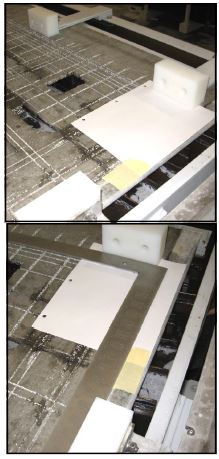
- Install the bumpers.
- If the backer board has a lot of cuts in the front
right corner, place several sheets of paper or a
piece of thin cardboard over the backer boards
as shown. Use masking tape to hold the paper
or cardboard in place. - Place the square as shown. Ensure the square
is tight to both bumpers. - Scribe a line on the outside edges of the
square.
Setting Table Offset – Single Table Model (cont’d)
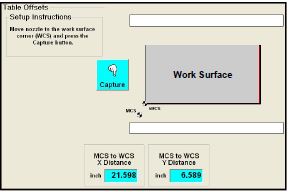
Capturing the Corner
- Remove all bumpers.
- Use the following steps to open the XY Dimensions Setup – Table Offset screen:
From the Main Menu press Setup button.
On the Setup Screen press Advanced Setup button.
Using the on screen keyboard enter the password: SUNRISE
On the Machine Setup – Advanced – Screen 1 screen press XY Limits Work Offsets button.
On the next screen (Soft Limits data), press the Table Offset button.

- Verify the nozzle/arbor assembly is at the Z upper soft limit.
- Using the pendant move the machine on the X and Y axis until the crosstravel assembly is positioned over the corner.
- Press the Nozzle Down button.
Setting Table Offset – Single Table Model (cont’d)
In next step, once the nozzle is with in one inch of the mark, switch to F1 (0.001) distance setting on the pendant for Z axis movements.
- Using the pendant position the nozzle so it is directly above
the marked corner. Continue to move on all three axis until
the nozzle is just about touching the corner mark.
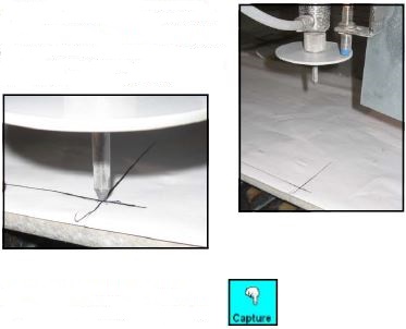
- Press Capture button on the Table Offsets screen.
NOTE: When pressed, the software automatically calculates MSC to WSC distance for both X & Y and then loads the values in the read only displays on the Table Offsets screen. - Press the Nozzle Up button.
- Using the pendant move the nozzle/arbor assembly on the Z axis to the upper soft limit.
- Using the pendant move the machine on the X and Y axis until the crosstravel assembly is in a safe position above the table.
- Return to the Main Menu by pressing:
OK on the XY Dimensions Setup – Table Offset screen – OK on the Machine Setup – Advanced – Screen 1 screen
Main Menu on the Setup screen
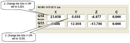
Presetting X & Y Work Offset
To minimized the number of time you have to cut the calibration square, set the X and Y offset values
as shown below.
- Use the following steps to open the Machine Setup – Advanced – Screen 1 screen:
From the Main Menu press Setup button.
On the Setup Screen press Advance Setup button.
Using the on screen keyboard enter the password: sunrise
Cutting the Test part and Setting the Blade to Nozzle Offset
Setting Blade to Nozzle Offset
The Blade to Nozzle Offset is used by the controller to line up the cuts between the blade and the nozzle. These values are critical to the quality of the edge that the machine makes. If the offset is not properly set, a vertical transition on the material’s surface is noticeable where the machine switches between a blade cut and waterjet cut.
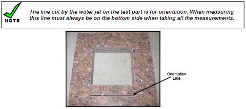
This procedure starts by cutting a test part which consists of a four inch waterjet cut square centered inside of an eight inch blade cut square. Once cut, the maintenance person measures how well the center of the waterjet square is lined up with the center of the blade square. These measurements along with the width are then used to calibrate the offset value. To align the Waterjet nozzle and the blade, follow the steps in this procedure on cutting and measuring the test part.
Cutting the Test Part
- Clean off the table.
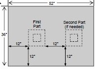
- Place a 3 centimeter thick material that measures a minimum of 36” x 52” on the Table.
- Place it so that the sides of the material are somewhat square with the table.
- Use the following steps to open the Calibrate Machine screen:
From the Main Menu press Setup button.
On the Setup Screen press Machine Setup button.
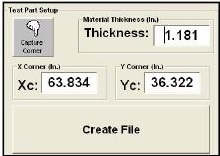
On the Machine Setup screen press Calibrate Blade to Nozzle button. - On the Calibrate Machine screen locate the Test Part Setup area (lower right corner).
- Enter the material thickness in the Thickness parameter display. Use a caliper to measure if
necessary. - Press the Down button to bring the nozzle down to just above the stone.
- Using the pendant manually jog the machine until the nozzle is over the point where the
bottom left corner of the test part will be located on the stone. - Once the correct location is achieved then press the Capture Corner button to set X Corner and Y Corner parameters.
Setting Blade to Nozzle Offset (cont’d)
Another way to determine Xc and Yc is to:
Measure from the center of the piece to the vertical bumper stop on the table and enter this value for Xc.
Measure from the center of the piece to the horizontal bumper stop on the table 1 Loading Arm and
enter this value for Yc.
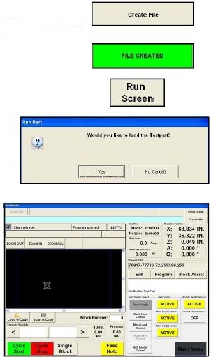
- Press the Create File button.
Once the file is created the button reads FILE CREATED in black letters on a green background. - Press the Run Screen button.
- When the Run Part dialog box appears press the Yes button. The proper files are loaded into the
machine. Once the files are loaded
the Run screen automatically opens. - Press the ‘Cycle Start’ button to
cut the test part.
- Remove the test part, rinse with the water, wipe it clean and use air to dry.
- Bring the piece over to the display along with the caliper that was supplied with the machine.
- From the Run Screen use the following steps to open the Calibrate Machine screen:
On the Run Screen press Main Menu button.
From the Main Menu press Setup button.
On the Setup Screen press Machine Setup button.
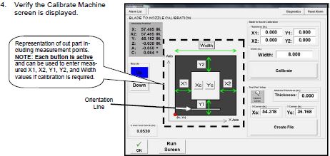
On the Machine Setup screen press Calibrate Blade to Nozzle button. - Verify the Calibrate Machine screen is displayed.
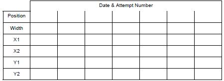
Measure the part in four places and take the average of these four measurements. Use the table shown
to record the measurements.
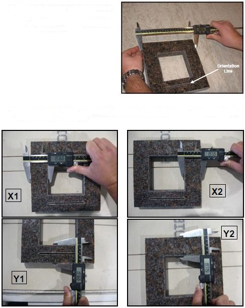
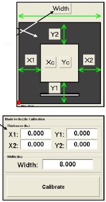
Enter the measured values by pressing the appropriate X1, X2, Y1, and Y2 button.
- Is the width 8.000 +/- 0.010 inches?
NO – Enter the value read on the calipers by press the Width button
Yes – Do not enter the measured value, use the default setting of 8.000 for the Width parameter.
Setting Blade to Nozzle Offset (cont’d) - Are all four X & Y numbers within 0.010 of each other? Yes – end of procedure, do not enter any numbers and do not press calibrate.
NO – calibration is required, go to the next step. - In the “Thickness (In.) area verify the values displayed are correct. If the width was changed, verify the correct value is displayed
and then press the Calibrate button. - Cut another test part to verify that the machinei s calibrated. Start at step 5 of this procedure.