
The following procedure illustrates assembly of Optimus Axis #6 Coil.
Scan to Read on Device:

Assembly

ASSEMBLY
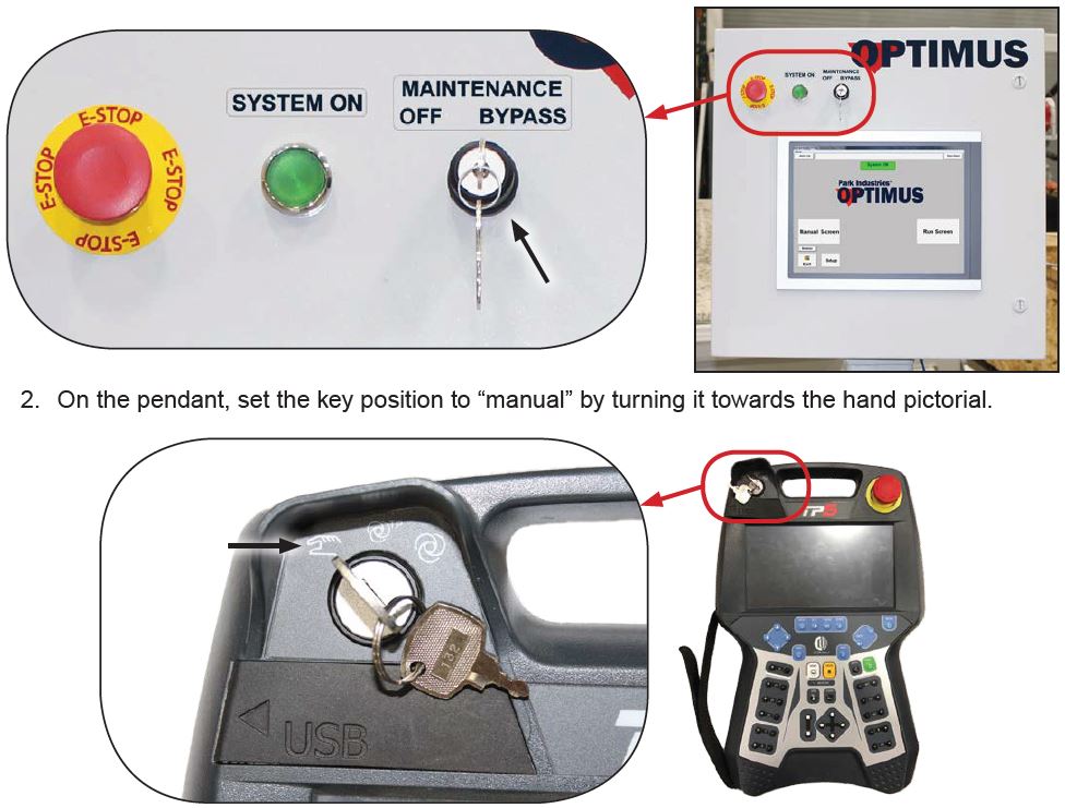
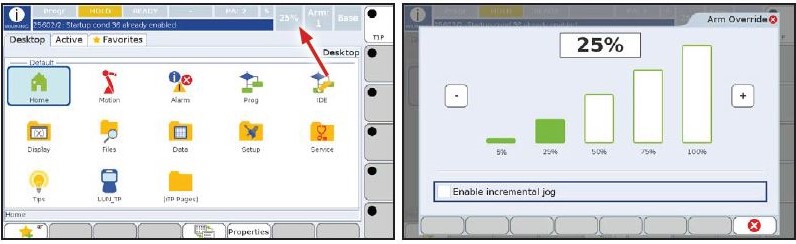
Set Arm Override Speed
Set Motion Control

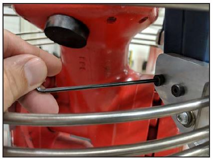
Position Arm for Assembly

for disassembly. Position axes J4 and J6 such that their positions are equal to zero as shown:
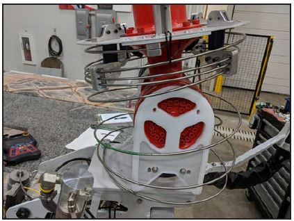
Positioning HP Coil
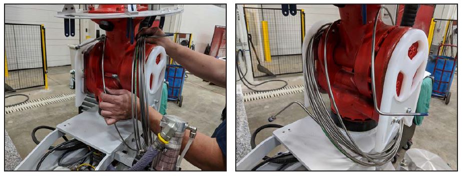
Assemble coil by threading it around the neck of axis four just above the robot wrist.
**Note: use masking tape or alike to protect painted surfaces while sliding the coil tubing
against the robot. Leave protective caps on the coils threaded ends to avoid damaging them.
** The coils thread ends are two different lengths. The longer end is oriented pointing
downwards. Begin installation as shown in the graphic below placing the longer end on the left.
Positioning Connections
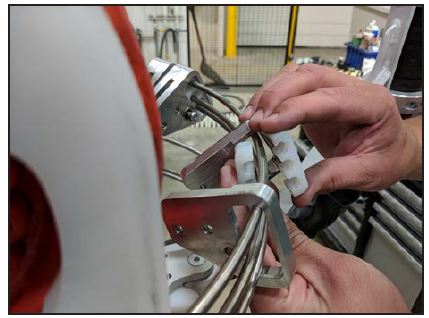
Loosely assemble the coils lower end high pressure connection to its corresponding 90 degree
fitting by performing the following:
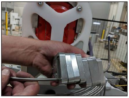
a. First, slide the gland nut onto the coils lower end hex first.
b. Apply blue goop to the threads of the coil’s lower end and thread the high-pressure collar
onto the threads until three threads of the coils end extend from the collar.
c. Finger tighten the gland nut into the lower 90 degree fitting.

Add clamp

Use a 3/16” hex key wrench, install two SHCS into the high-pressure tubing clamp and tighten
fully.
Placing Coil Hangars

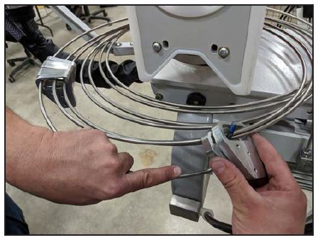

Thread coil hangers onto coil all at once being certain to follow the correct orientation as shown
in the graphics below.
a. ***IMPORTANT: The correct orientation of the coil hangers is critical to further assembly.
b. Pass the top coil end through each coil hanger after each revolution until each coil
hanger has three revolutions of tubing inside it.
Positioning components


Insert the top end of the coil through the halo hole
First, slide the gland nut onto the coils upper end, hex first.
Apply blue goop to the threads of the coil’s top end and thread the high-pressure collar
onto the threads until three threads of the coils end extend from the collar.
Finger tighten the gland nut into the lower 90 degree fitting.
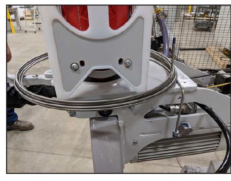
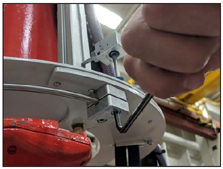
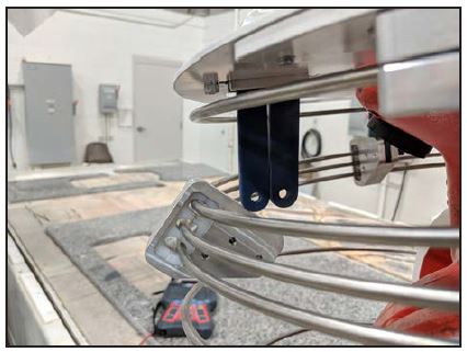
Halo Connection
Use a 3/16” hex key wrench, install two SHCS through the high pressure tubing clamp into the
halo, securing the coil to the halo.

Locating Coil Hangars
Now position the last hanger pair threaded onto the coil at the position corresponding to slightly
greater than one revolution from the coils top. Working clockwise from the top, position the
remaining hanger pairs at their corresponding linkage positions.
a. After locating the coil hangers to their respective halo linkages, proceed to insert two
UHMW coil slides into the hanger pairs.
b. Using a 5/32” hex key wrench, assemble four BHCS into the coil hanger pairs.
c. Using a 1/8” hex key wrench, assemble eight SHCS into the coil hanger bodies.

Tighten HIP connections
Using a 5/8” open end wrench and adjustable wrench, fully tighten the coil’s high pressure
connections to 15-25 foot-pounds.
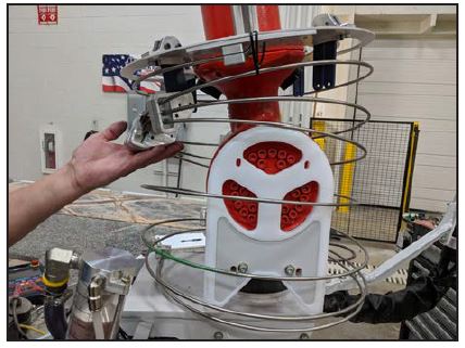
Finalizing mounting and connections
IMPORTANT – Examine the assembly, verifying the following:
a. On the Pendant confirm axes 4 and 6 are positioned at zero degrees.
b. Starting from the top of the coil working down; confirm one full revolution is not contained
in any coil hanger and is also outside the coil hanger linkages.
c. Confirm all four hangers are supporting three coils.
d. Confirm 3.25 revolutions are free floating from the hangers to the lower clamp
e. Confirm 7.25 coil revolutions from the upper coil clamp to the lower coil clamp as shown.
