
Use this procedure when miter cuts are coming out the incorrect size. It is very important to go through each step in the order listed.
Scan to Read on Device:

Setting Z Offset
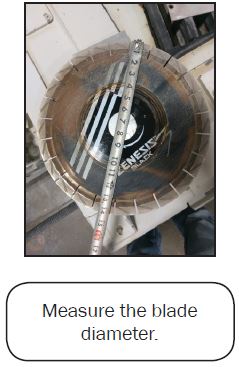
1a. Remove the blade, measure the EXACT diameter. You MUST remove the blade to do this or use the Z offset jig.
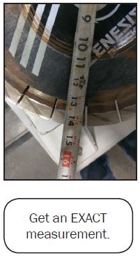
If the blade diameter is measured incorrectly the following steps will be negatively affected
1b. Install the Blade again
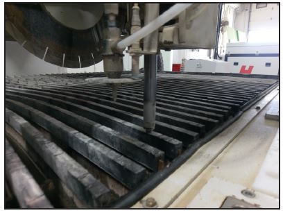
1c. Lower the Z Rise and Fall and lightly touch the table top. Find an area of the table which is not all cut up
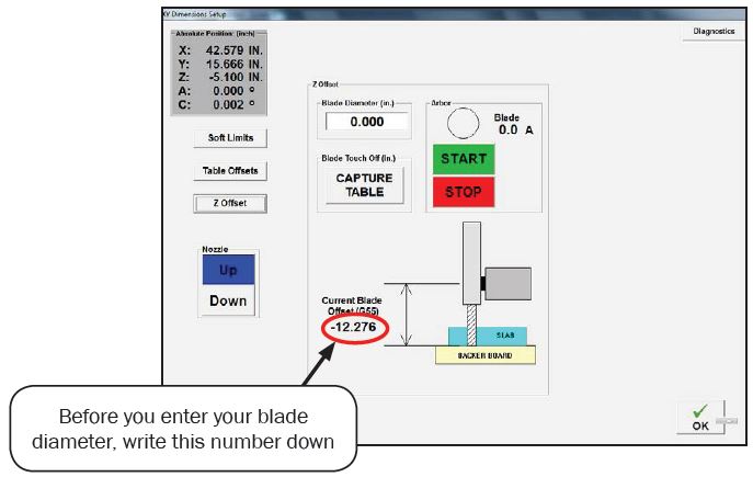
Once the blade is touching the tabletop, from the Main Menu, go to Setup, Then Advanced Setup, enter SUNRISE for the password, in the lower right corner, press XY Limits & Work Offsets. Now on the left side of the screen there is a button that’s labeled Z Offset, press that. Your screen should look like the one below.
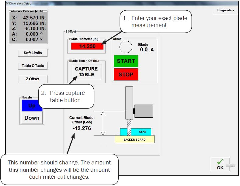
Verify the Blade Diameter
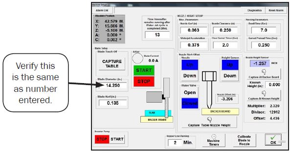
2a. From the Main Menu, go into the Setup screen, and then to into Machine Setup. The number int the Blade Diameter box should be the same as the number you entered in the Advanced Setup Screen. If it is, proceed to the next step. If it isn’t press the capture table and it should change to the correct number.
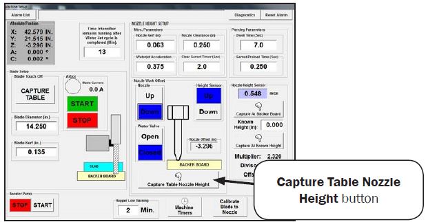
Capturing the Table Nozzle Height
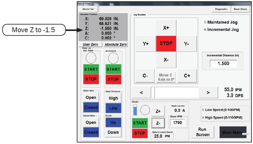
3a. In the Machine setup page, press the Down button for the nozzle
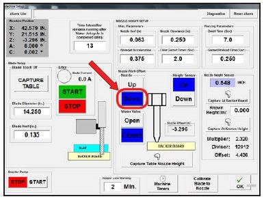
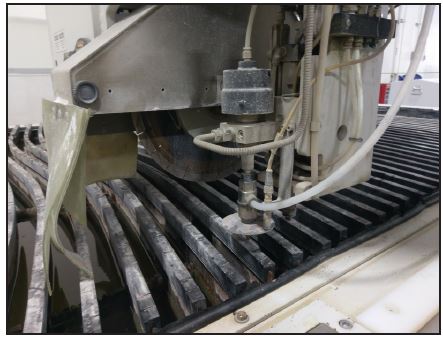
3b. Now use the pendant to slowly lower the nozzle so it just touches the table top (see photos below)
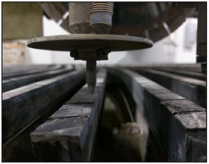
3c. Press the Capture Table Nozzle Height button
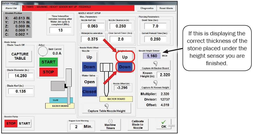
Calibrate Height Sensor
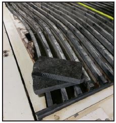
4a. You’ll need two pieces of stone for this procedure.
4b. Go into the machine setup page. Move Z axis Rise and Fall to 0.00 and drop the nozzle down and bring Z down until its about 1/4″ away from the two stacked materials.
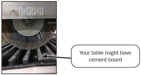
4c. Move the machine so the height sensor will drop down on a rubber slat or a good part of cement board
4d. Under the Height Sensor section press the Down button to lower the height sensor then press the Capture at Backer Board Button
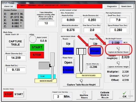
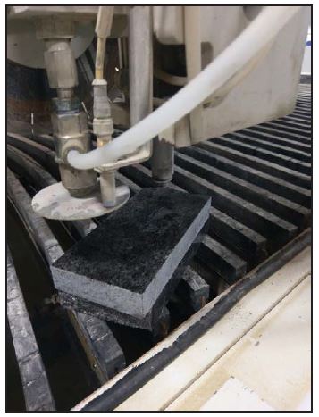
4e. Using a hand caliper, measure the thickness of two pieces of stone. Raise the height sensor up and place both pieces under the height sensor
4f. under the Height Sensor section press the Down button to lower the height sensor on the stone, enter the measured thickness of both pieces of stone into the Known Height box, then press the Capture at Known Height button
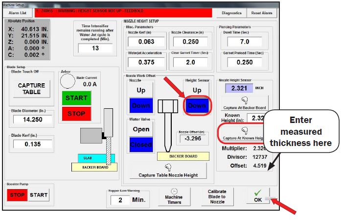
4g. Under the Height Sensor section press the Up button to raise the height sensor, remove one of the pieces of stone and press the Down button to lower the height sensor onto the single piece of stone. The correct material thickness should appear in the box as shown
Verifying measurements
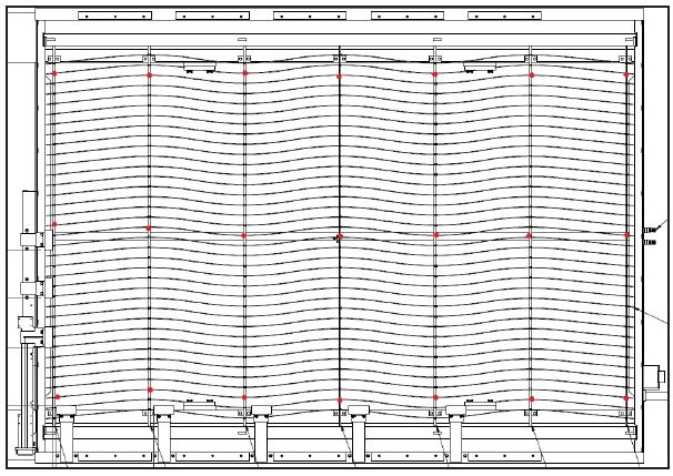
Verify the table is level to the machine. Using the height sensor verify the table is level. (The best locations to check are where the red dots are located on the following pages. There is an example for both tilting and non-tilting tables) If the table isn’t level, the machine will not be able to perform correct miters
- Verify the parts with perpendicular cuts (saw is oriented straight up and down) are being cut to the correct size. Check any backsplash, countertop, lengths, widths and verify they are coming out the correct size. If they are NOT, this procedure will not help.
Verifying level

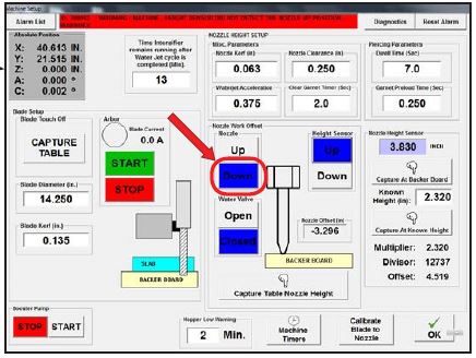
Position the height sensor near the front right corner of the table. Under the Nozzle Work Offset section press the Down button then under the Height Sensor section press the Down button. Verify the height sensor reading is close to 0.000.
If the height sensor position reads zero, proceed to the next step, if it doesn’t, preform the height sensor calibration before checking the flatness of the table.
This picture is for NON-TILTING tables. The best places to check would be where the red dots are.
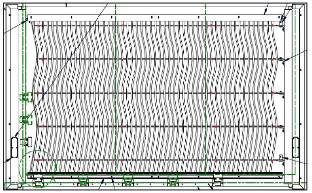
This picture is for TILTING tables. The best places to check would be where the red dots are.
Once you verify the table is level within .064, you can now proceed with cutting a calibration square. If you find it isn’t, please call Park Industries Customer Service and we can help determine the next step.
You are now finished setting up the machine. Run a test part and check measurements. If you continue to have issues, please contact Park industries.