
A step by step procedure to calibrate the SL Laser to a Destiny or Titan Router table
Scan to Read on Device:

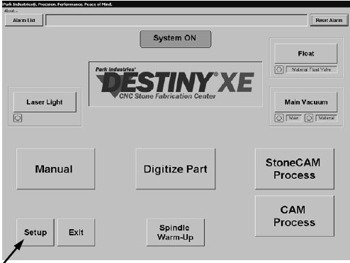
Power up the Destiny XE / Titan and start the Front end software. When everything is up and running press the Set-up button on the main page. Inside the Set-up Page press the ‘Advanced Setup’ button. Enter the Password for the Advanced Set-up page.
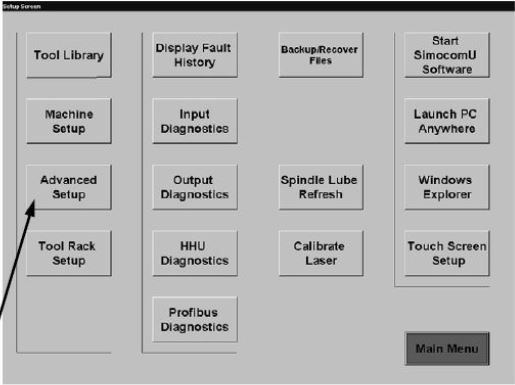
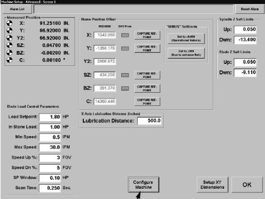
Once inside the Advanced Screen press the ‘Configure Machine’ button and enter the password for access to the Configure Machine Page.
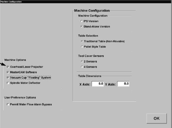
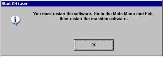
Be sure that the Overhead Laser Projector option is checked. When you check the overhead laser option a message box will appear indicating that you must restart the Machine Software. Do NOT exit out of the software at this time. OK out of the Configure Machine page and OK out of the Advanced Screen.
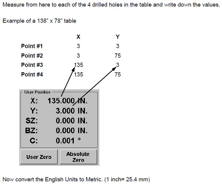
Physically, take a moment to walk around the Destiny XE/Titan table. You will find four holes, one in
each corner approximately 3 inches from each side.
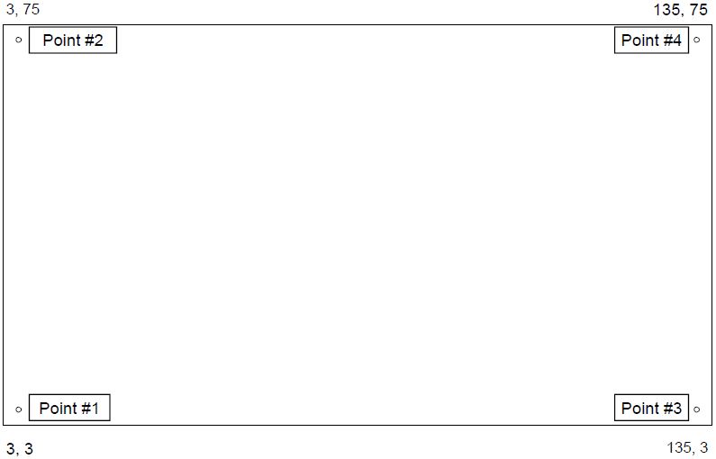
Note: These numbers are for example only of a large table (138”x78”). The holes on your table may be drilled in different location than shown in this example. Once you have found these holes, return to the Destiny XE/Titan control panel and enter the Manual Screen.
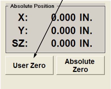
Now, using the Destiny XE/Titan laser cross hairs (the RED cross hairs on the Machine, find the front left corner of the table. set this as User Zero.
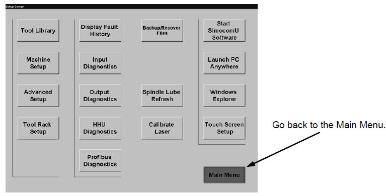
MOVE the DESTINY XE/Titan Head to the backcenter to prevent it with interfering with the overheadlaser calibration. Go to the “Main Menu” Exitthe Destiny XE/Titan software, then turn off Auto- SL by finding the symbol in the bottom right corner and tap it to turn it off.
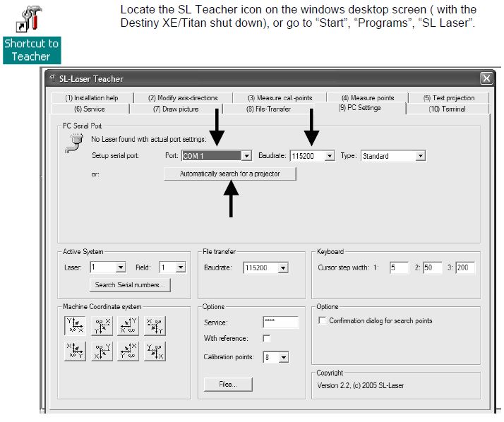
When Teacher starts up, it will automatically go to (9)
PC Settings. Change the Port = COM 2, Baud rate =115200 and Depress “Automatically search for a projector”. This search can take a fair amount of time so be patient. A message box may come up that says that a projector was found but it had different settings. It is ok to accept this. Once the laser is communicating with the PC, Teacher
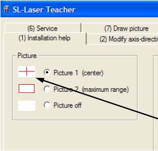
will switch over to (1) Installation help and shine the cross hairs on the table.
Please take this opportunity to confirm that the center of the crosshairs appear near the center of the table. If not, you will need to physically adjust the laser. It does not have to be exact. However, it is best if you can get it close. Then click “Next”.
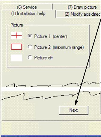
Picture 2 projects a VERY large rectangle. The DESTINY XE/Titan table needs to lie somewhere inside this rectangle. It DOES NOT have to match in size. on the bottom of the installation help tab is the NEXT button. Press it now to advance to the next modify axis screen
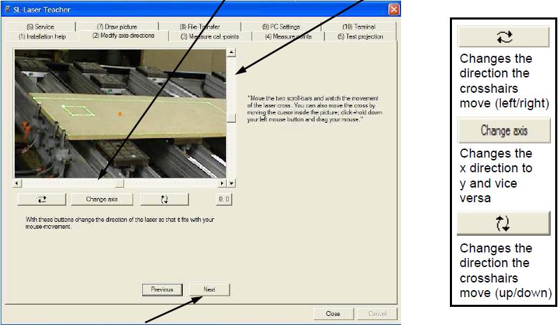
2. Modify axis-direction. Verify that the green square moves the correct direction. Using the
slider bars check that if you click to the left the box moves left, click up box moves back on the
table, etc. Press next to advance to Measure Cal Points
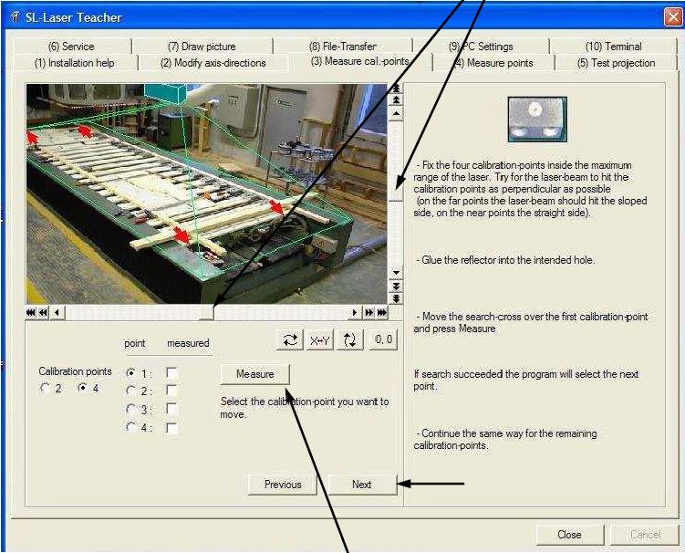
3. Measure cal.-points
You will be calibrating the 4 permanently mounted reflectors using Tab 3. Make sure the front
left calibration point is inside box C1. Move the box as needed using the sliding axis next to the
picture
Once the reflector is inside the box, depress the “Measure” button. The laser will scan within the
square and find the reflector. Repeat this with the other three corners making sure they are
number as follows: back left is #2, front right is #3 and back right is #4.
Once all four points have been measured, click the “Next” button to move to (4) Measure points.
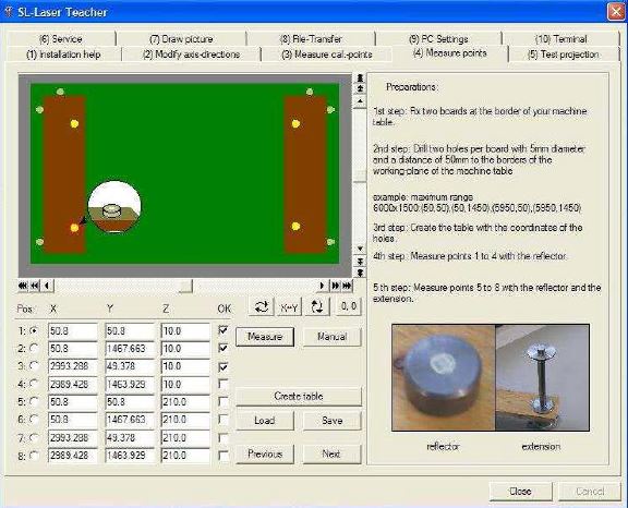
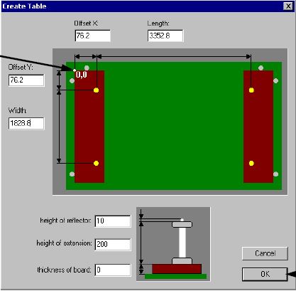
4. MEASURE POINTS – The first thing to do is press the “Create Table” button. The screen below will show up. In this screen
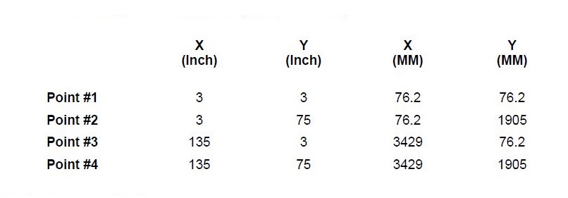
the operator will enter the measurements of the holes in the table (be sure to use the metric numbers,
MM). Once this is done hit “ok” and these numbers will be entered into the proper column from the
“(4) Measure points” tab/screen.
The first thing to do is press the “Create Table” button. The screen below will show up. In this screen
the operator will enter the measurements of the holes in the table (be sure to use the metric numbers,
MM). Once this is done hit “ok” and these numbers will be entered into the proper column from the
“(4) Measure points” tab/screen.
Note: all of these dimensions entered are based off of the frontleft corner of the table. Whenentering the length and width
dimensions in this screen besure to subtract the distancefrom the corner of the table tothe first hole. In this example for
the Length: 3429-76.2=3352.8Width:1905-76.2=1828.8Be sure to enter 10MM for theheight of the reflector and200MM for the height of extension.
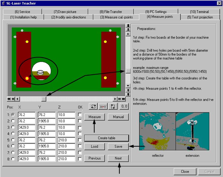
Start at Pos. 1, place the reflector in the front left hole in the table, make sure the box labeled
T1 encompasses the reflector. If the box does not encompass the first point use the sliding
axis bars the same way they were used to surround 4 permanently mounted calibration
points from page 10. If the laser box surrounds the first point press “Measure”. You will then
complete points 2, 3 & 4 in the same manner. For points 5, 6, 7, and 8, use points 1 thru 4’s
X, Y location but place the reflector on top of the 200 mm extension. Make sure you follow
the positioning as indicated in the display. Once this is completed for all 8 points press
“Save”.
Once you have measured all of the points a display box will appear that will indicate your
“Quality (point)”. The first number indicates your worst level of accuracy (the value must be
less than 1.0) the number in parenthesis tells you at what point it occurred.
“Next”
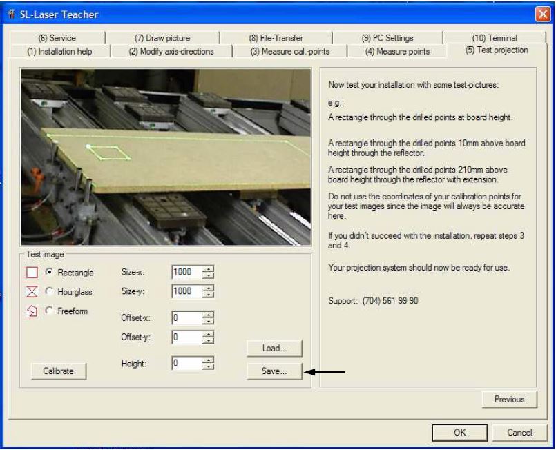
The “Rectangle” and “Hourglass” should reflect on the front left corner of the table and be
1000mm (1 m) x 1000mm (1m) or about 3 ¼ ft by 3 ¼ ft. Physically measure this rectangle and
hour glass to be sure the laser is projecting the right size and location on the table. Once you have
reached this point in the process you will need to “Save” the calibration information.
The Destiny XE/Titan software can be started again. There is one more test to run on the Destiny
XE/Titan to double check the accuracy of your overhead laser. Once the software is loaded follow
the directions from pages 1 and 2 to get into the “Advanced Setup” screen.
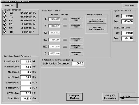
Press the Setup X,Y Dimensions button
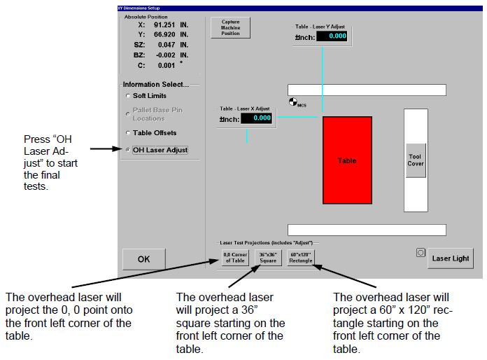
ONCE all these tests have been done the Destiny XE/Titan overhead laser is calibrated.and ready to RUN.