
Dialing the blade to be true with the Machine X, Y & Z axes
Scan to Read on Device:

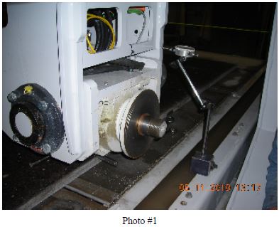
Position the CrossTravel to setup the Dial Indicator.
1a. Remove the blade, and the blade shroud.
1b. Attach the dial indicator to the edge of the water tank. (Ref photo #1).
Measuring X axis without Blade first.
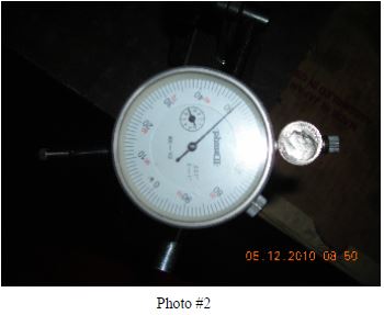
2a. Once the dial indicator is positioned as in photo #1, set the dial indicator to zero, and move the X axis in the
positive direction. Note: Be sure to use a coin or washer to hold the needle back as you move the axis. Be
careful as to not bump or move the dial indicator, only slide the needle out. (Ref photo #2).
2a Based on what reading you get from the dial indicator, you will need to rotate the C axis either direction. Move the C axis half of the distance you were off from zero on the dial indicator. For example, if the dial indicator read zero on the first side, and .010 on the second side. Rotate the C axis until the dial indicator reads .005.
2b. Repeat steps 3 through 5 until both sides read a maximum of +/- .001, without having to move the C axis.
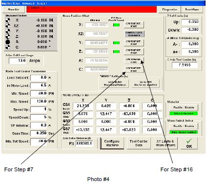
2c. From the main menu on the operators screen, go to “SETUP”, then press the “ADVANCED SETUP” button. The password is “SUNRISE”. In the Advanced Setup screen push the button “Capture Ref Point” next to the “C” axis position. If a message pops up, click proceed to Re-reference that axis, but do not restart the machine yet. (Ref photo #4). Once you have captured the C axis, is it important not to move this axis after that. If the axis is moved, the rest of the dialing procedure will not be correct.
Measuring the X axis with Blade mounted on arbor.
3a. Replace the blade on the arbor shaft, do not install the shroud at this point. Attach the dial indicator as in Photo #5. Make sure to keep the needle of the indicator just below the white blade flange. Mark the blade with a marker, were the needle of the indicator makes contact with the blade, this will be your reference mark. Then set the dial indicator to zero, and move the X axis in the NEGATIVE direction. Once you have reached the other end of the blade, rotate the blade so the reference mark is once again were the needle contacts the blade, (Ref photo #6).
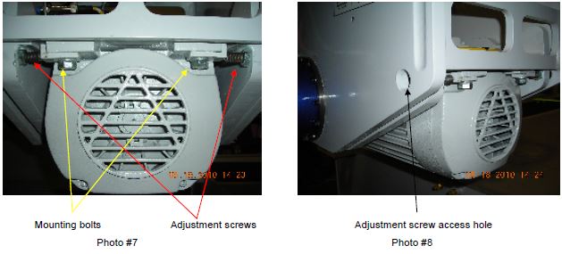
3b. Based on what reading you get from the dial indicator, we need to shift the whole arbor motor. On the backside of the motor, there is adjustment screws to shift the motor. (Ref photo #7 and #8). Loosen the mounting bolts slightly before shifting the motor. Be sure to shift the motor in the correct direction. Shift the motor half of the distance the dial indicator is off from zero. For example, if the dial indicator read zero on the first side, and .010 on the second side. Shift the motor until the dial indicator reads .005.
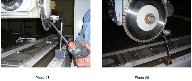
3c. Repeat steps 8 & 9 until you have a reading of between -.002 and -.003. Make sure the reading is a NEGATIVE reading when moving from left side of blade (Ref photo #5) to the right side of the blade (Ref photo #6).
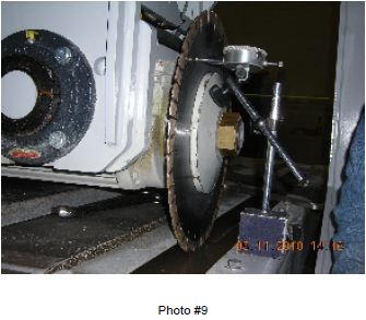
3d. Now we need to dial in the A axis (Miter). Position the dial indicator as in photo #9. Be sure to position the blade so it will drop into the water, and not hit the frame of the tank
Measuring A Axis with Blade on Arbor
4a. Again, take a marker and mark the blade with a reference point. You may want to move the Z axis up and down, to make sure you can reach your reference mark at the top and bottom of the blade.
4b. Set the dial indicator to zero on your reference mark, you can start on the bottom of the blade or the top, it will not matter. Move the Z axis so the dial indicator is on the opposite side of the blade from where you started.
4c. Based on the reading from the dial indicator, you will need to move the A axis either positive or negative direction. Again move the A axis half of the distance the dial indicator is off from zero.
4d. Repeat steps 13 & 14 until you have a reading of a maximum of +/- .002 on the dial indicator
4e. Once the A axis is set, push the “Capture Ref Point” for the A axis (Ref photo #4). Click ok to proceed with the re-reference.
4f. Exit the Fusion software, and shut down the computer. Once the computer has shut down, turn power off to the machine. Make sure to leave power off for at least 30 seconds. After 30 seconds, power up the machine and launch the Fusion software. A message will pop up cautioning that one or more axis has been re-referenced, click ok. Re-install the blade shroud, machine is now ready to cut.