
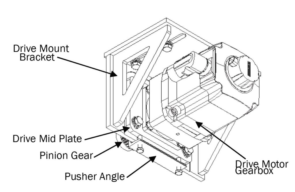
This document illustrates the steps to assemble / mesh the Fusion X axis drive pinion gear and gear rack and referencing the drive motors. If you have any questions, contact Park’s customer service at 1-800-785-3391.
Scan to Read on Device:

Lowering the assembly
These steps start with the pinion gear in the down and extended (out) position. On both sides, snug the mounting bolts to a point that removes all free play but still allows for the movement of the bracket or plate wih a minimum effort.
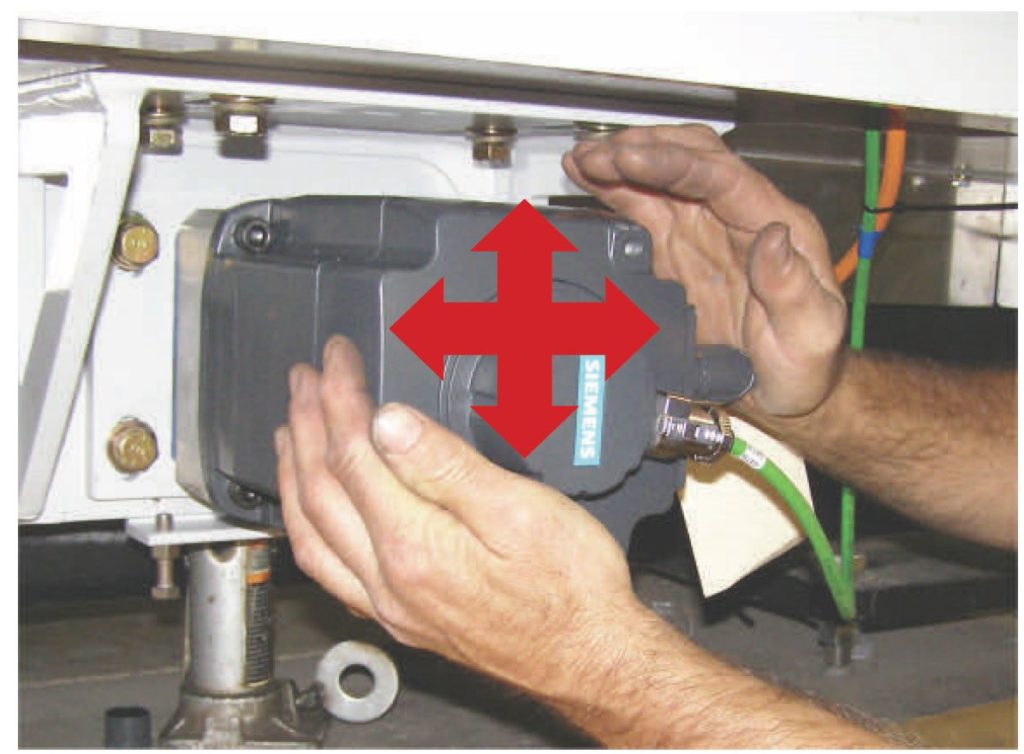
Positioning the bridge
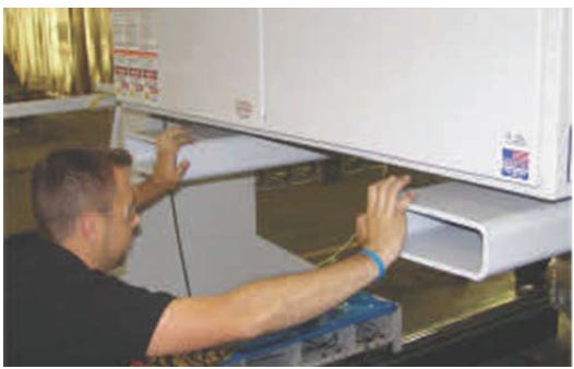
Push the bridge back and forth (positive direction 8 to 10 feet ) then push in the negative direction (8 to 10 feet) on the X rails. Repeat this a couple of times to insure the bridge is in its neutral position.
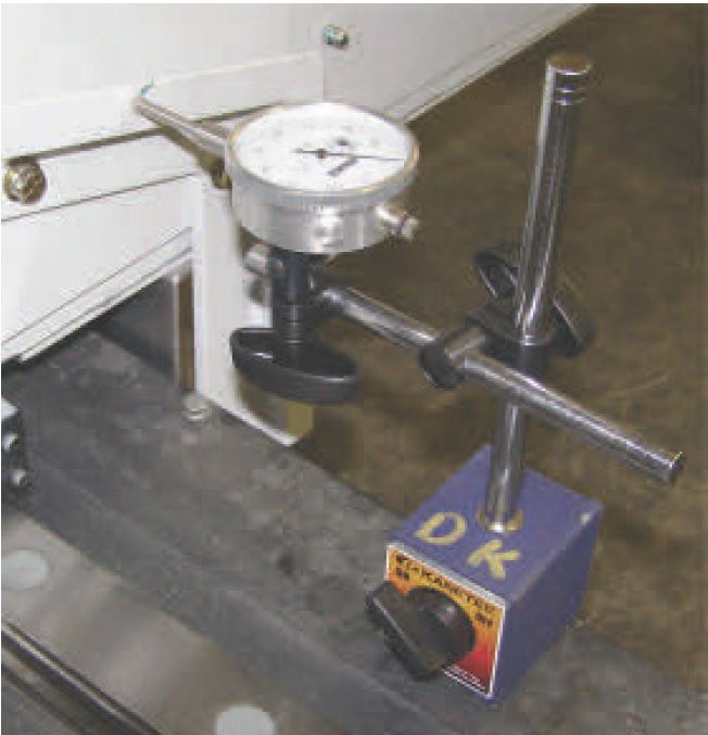
Place a dial indicator as shown on each bridge leg
Set up a dial indicator on each X THK rail to measure gear backlash.

Zero both dial indicators

gear alignment
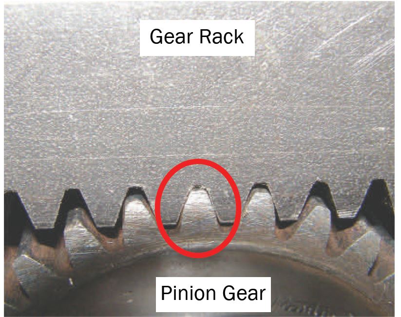
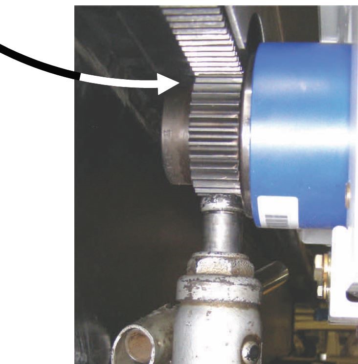
The goal of the next step is to align the pinion gear with the gear rack. When moved into position, the pinion and rack teeth should squarely mesh/align without any bridge movement (dial indicator needle does NOT move).
Align the pinion gear to the gear rack as follows: Move the pinion gear close to the gear rack.
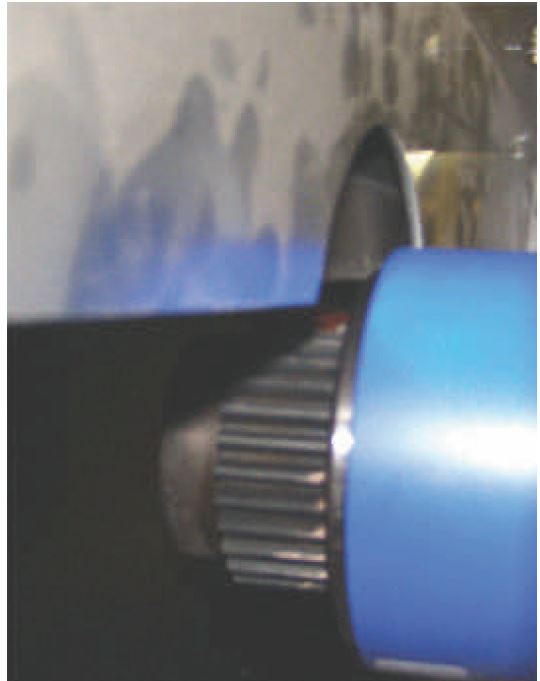
Visually check alignment. Will the rack and pinion mesh as shown above?
YES – go to step 6.
NO – go to next step.
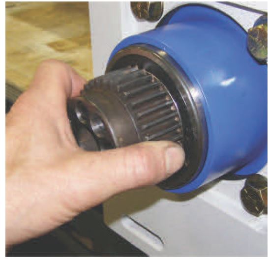
Lower the motor, rotate the pinion gear and
then repeat steps 5a and 5b.
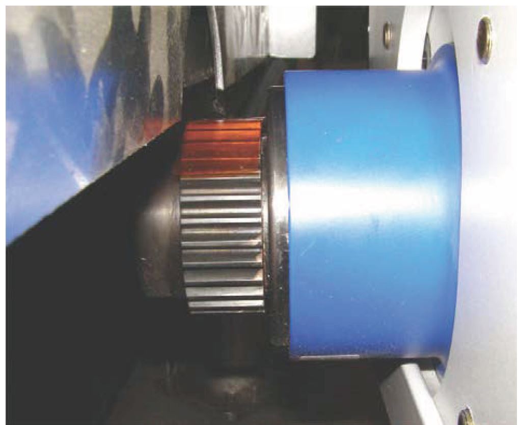
Place a 0.002 plastic shim on the pinion gear.
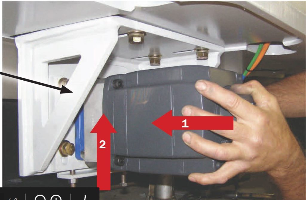
Meshing the pinion gear teeth and rack teeth
Position the drive motor so the pinion is aligned with the gear rack.
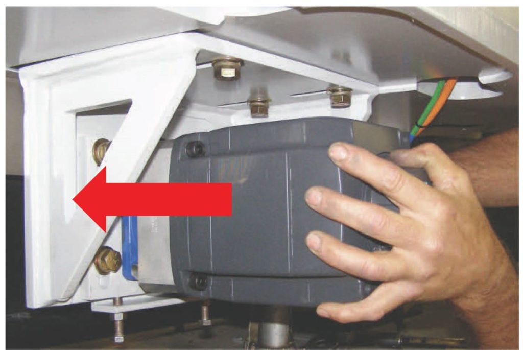
Positioning the Motor
Place a bottle jack under the pinion gear, verify the shim is still on the gear and then slowly jack the gear into the gear rack until you have a snug fit (moderate jack pressure).
Placing the Hydraulic Bottle Jack
Rotate the gear left and right slightly to ensure the gear is squarely seated in the gear rack. Check jack pressure.
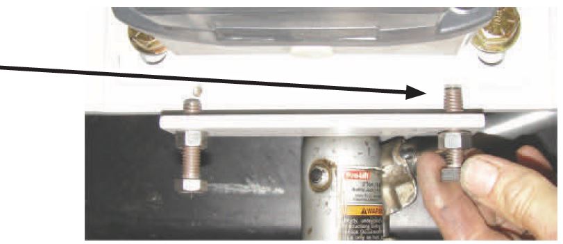
Tighten the four drive mid plate bolts.
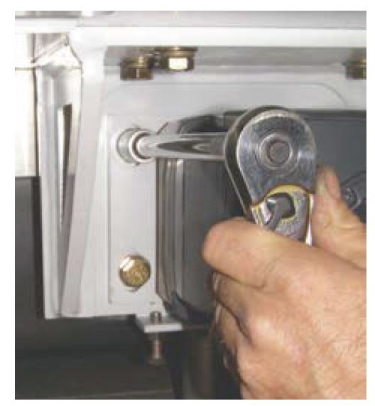
Set the pusher bolts.
Set the pusher bolts.
Setting the pusher bolts
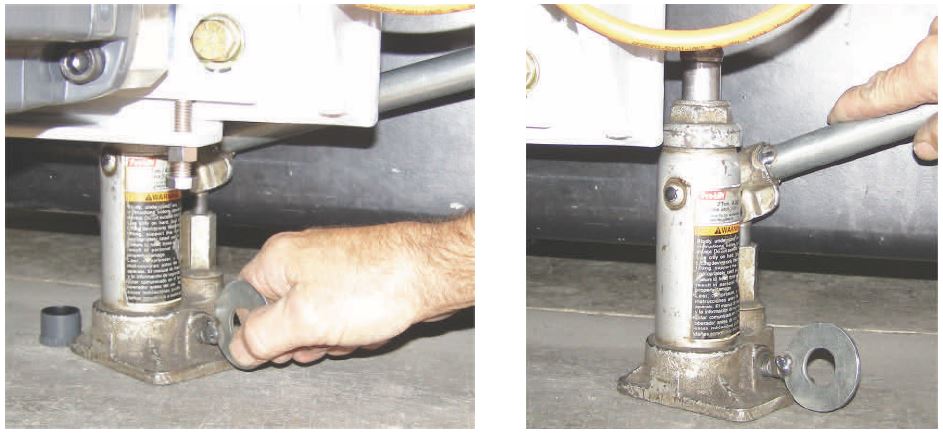
Lower the jack and then remove the jack.
Removing the Hydraulic jack
Have both sides been set? / Yes – Go to step 16. / No – Execute sets 5 thru 14 for the remaining side
Reference X axis. Using standard procedures, reference the X Axis
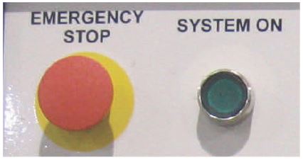
Verify the machine is in the Emergecy Stop State (button pushed in). Do not Change the position of this switch until the drives have been Syncronized. Turn on power to the Fusion and initiate the Fusion Software.
When the Fusion Software boots up, press the setup button on the main screen. On the Setup screen, press the advanced setup button. On the Advanced Setup screen, Press Capture Referrence point.
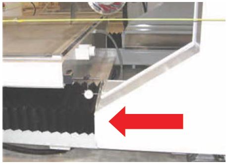
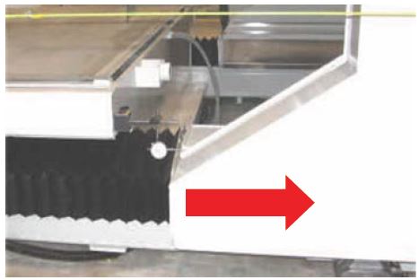
- Pull back the X axis bellows covers if attaching the dial indicator magnetic base either on the X rails or water tank. Both X rails gear backlash should be measured at the same time. This will increase the accuracy of the backlash engagement procedure.
- Once both dials are in place, “zero” the needle prior to measuring.
Make sure the Fusion System is turned on and both dial indicators are ‘ZERO’.
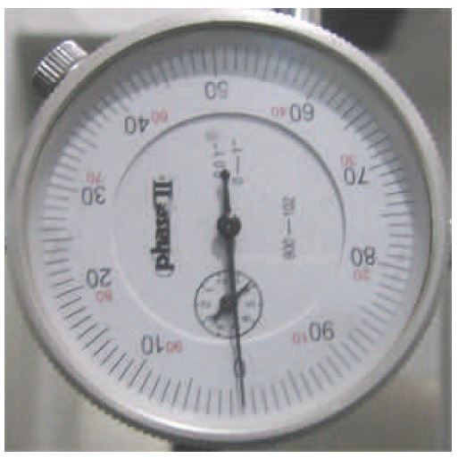
While observing the dial indicator physically PUSH Hard (the system is ‘ON’) the bridge toward the dial indicator. Observe and record the dial reading.
While observing the same dial indicator physically PUSH Hard (the system is ‘ON’) the bridge away from the dial indicator. Observe and record the dial reading.
Add the values recorded in steps 4 & 5. If the sum is greater than 0.006″ there is excessive free play between pinion gear and gear rack. The entire gear alignment procedure steps must be done over.
- FINAL CHECK.
- Use the following steps to verify the X Axis drives are not binding during normal movement.
- Apply power and initiate the software. using the pendent or manual screen controls move the bridge to the X-Axis minus the soft limit.
- Move the bridge about two feet in the X + direction and stop movement.
- E-Stop the machine.
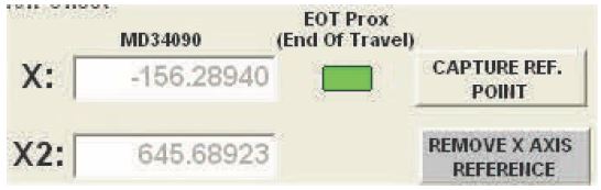
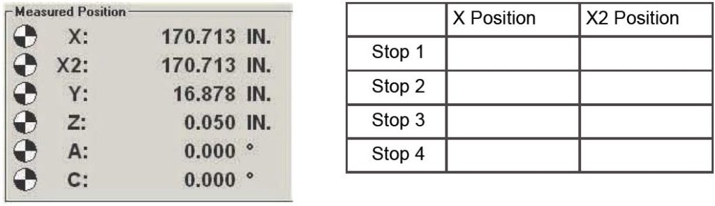
- On the Machine Setup/Advanced Screen record the X and X2 Measured positions (grid pictured above). Repeat over the entire length of the machine.
6. Disengage the E-Stop and repeat steps over the entire length of Machine.
Summary – the best scenerio is to have the difference between X and X2 position less than 0.005″ inches at all Stop positions. If all Stops show a difference greater than 0.005″ the entire gear alignment procedure must be done over. If only one stop shows a difference slightly greater than 0.005″ the gear alignment is satisfactory.