
introduction:
This water kit upgrades the 5/8″ recycle water line with a 3/4″ rubber hose for an increased flow rate. The halo, or water ring, refers to the recycled water.
It consists of the following upgrades:
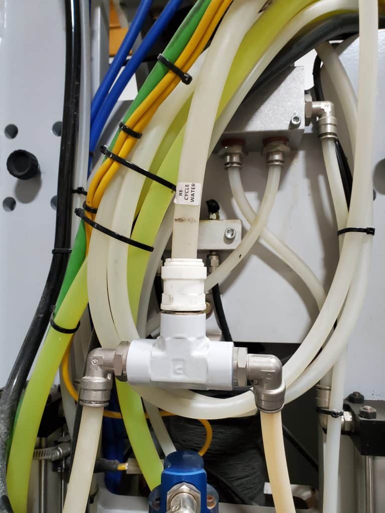
The water splitter at the saw water ball valve assembly is replaced with one that has 3/4″ fittings.
The 5/8″ clear water line that comes from the splitter and into the recycle water ball valve assembly is replaced with 3/4″ rubber hose.
The 5/8″ clear water line that exits the recycle water ball valve assembly and goes to the Y-block is replaced with 3/4″ rubber hose.
The 5/8″ to 1/2″ Y-block assembly that branches off to the halo is replaced with a 3/4″ to 5/8″ Y-block. The Y-block is mounted directly above the spindle water union.
The two 1/2″ fittings on the halo are replaced with two 5/8″ fittings.
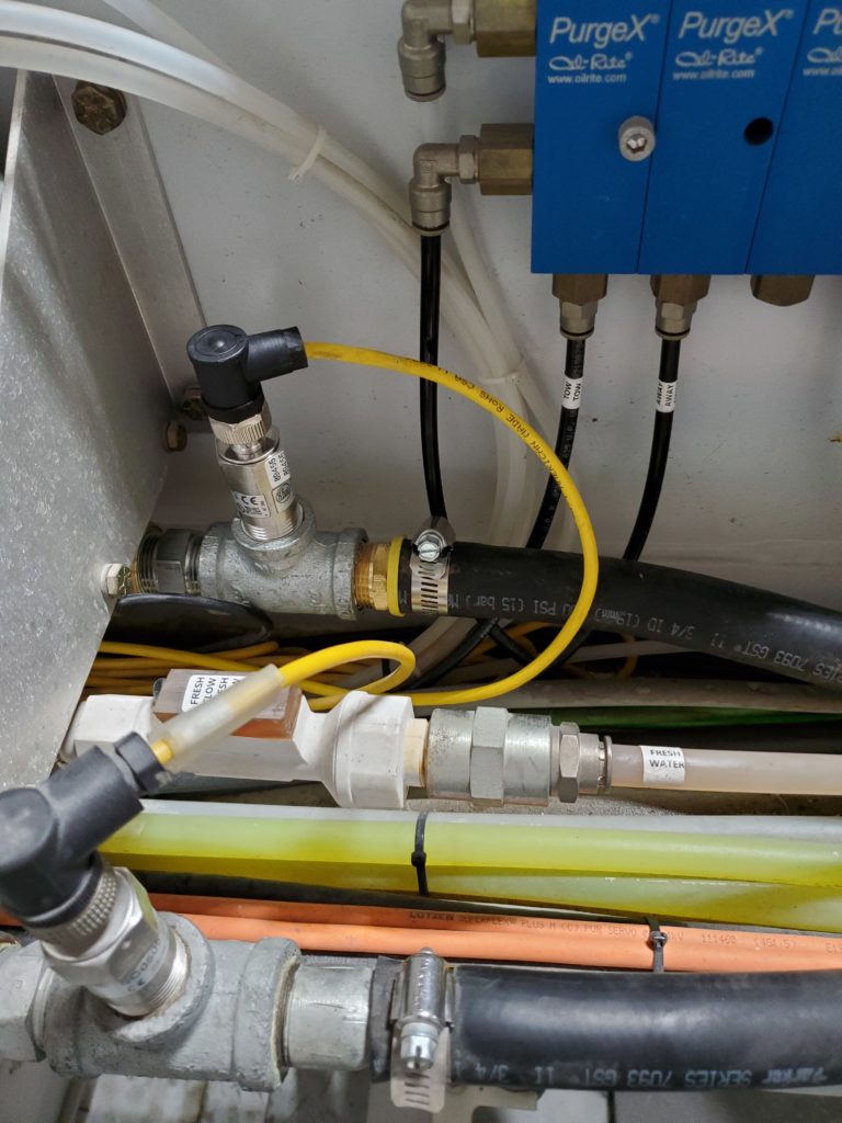
In order to adjust the halo water flow rate, open or close the hand valve that’s connected to the infeed side of the recycle water ball valve assembly. Water flow results also depend on water supply.
Scan to READ on Device:

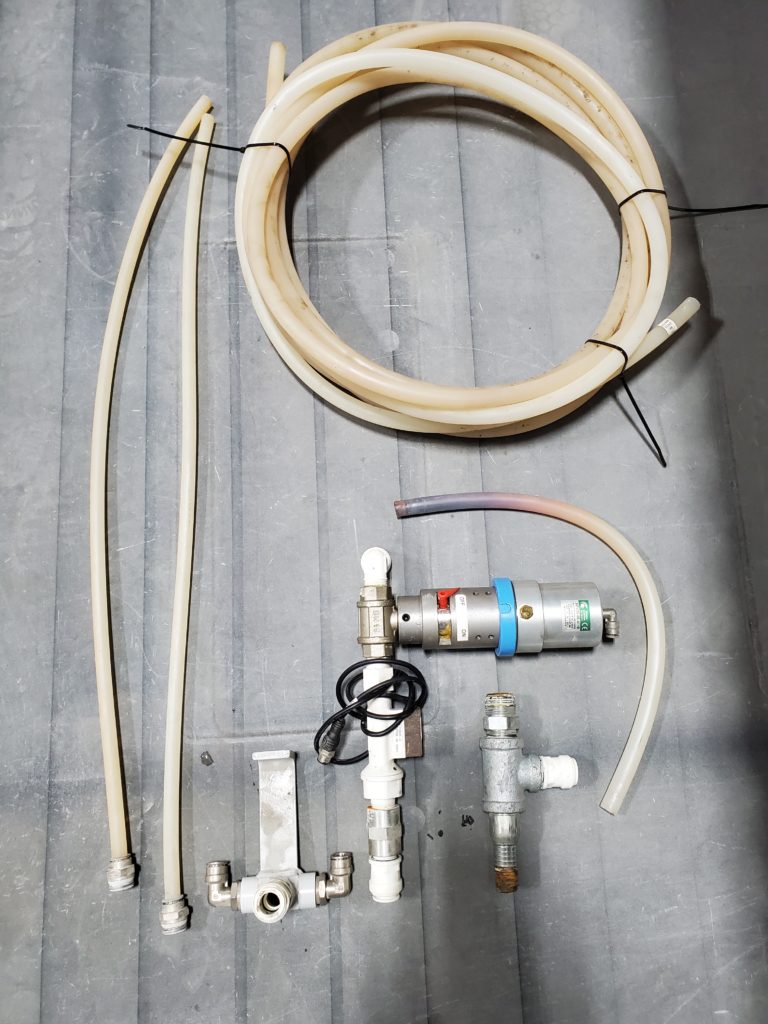
Parts list for kit 100384.
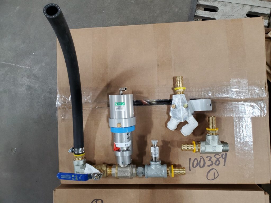
- 3/4″ Recycle water ball valve assembly
- Water supply Y-block
- Water Splitter
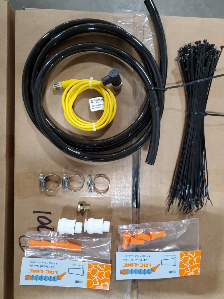
- Flow switch cable
- 1/4″ Loc line nozzles: 8
- Hose clamps: 3
- 5/16 x 3/4 bolt and flat washer: 1 each
- 5/8 x 1/2 fittings: 2
- 11″ black cable ties: 50
- 5/8″ OD black poly tubing: 96 inches
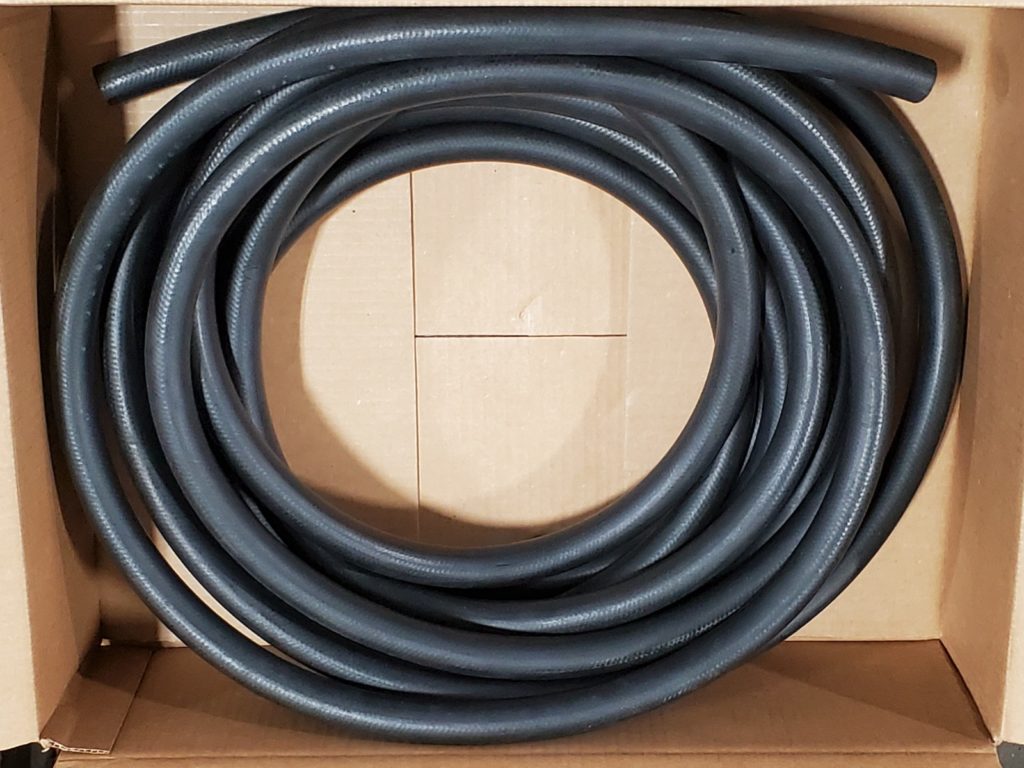
- 3/4 ID water hose
Tools needed
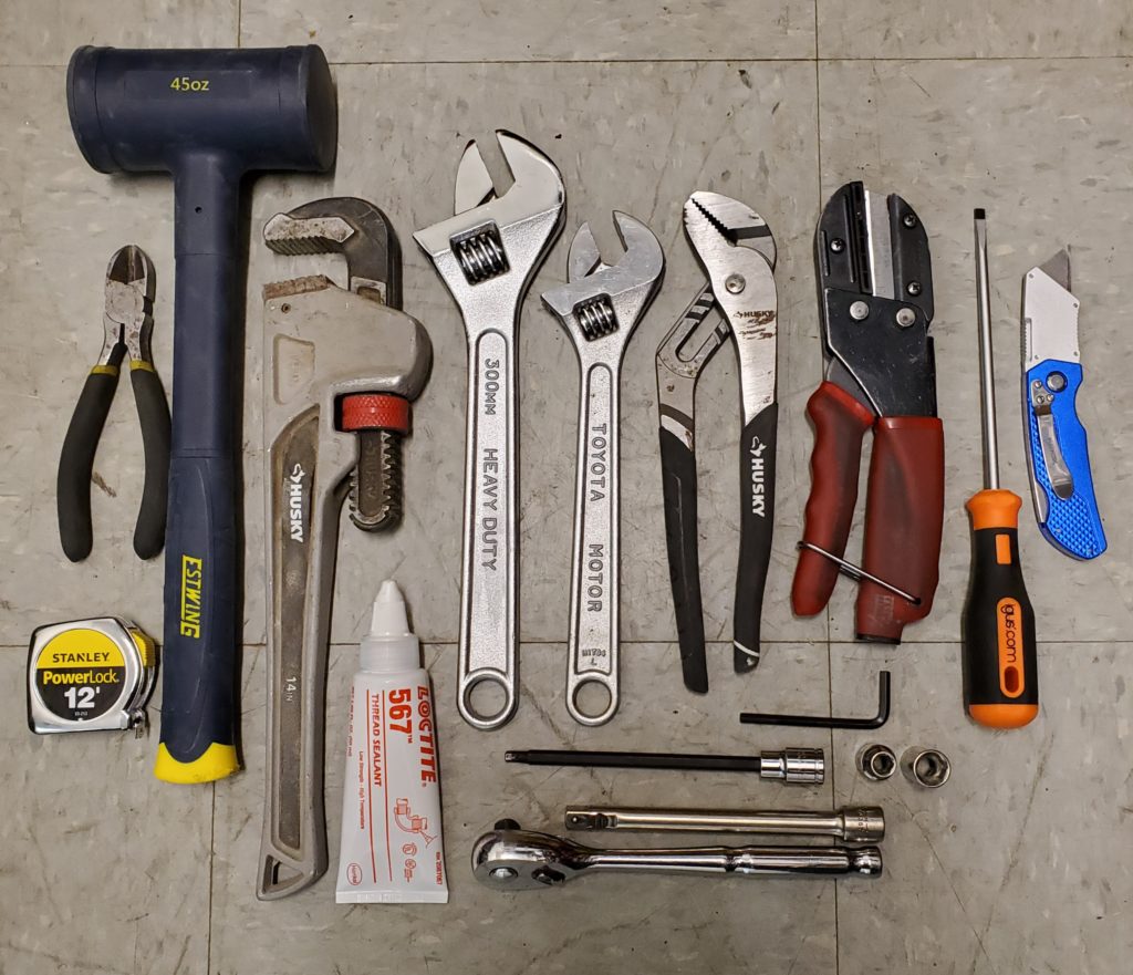
- 3/8 drive ratchet
- 3/8 drive: 6″ extension
- 3/8 drive sockets: 5/16, 1/2
- 3/8 drive: 3/16 hex extension
- Allen wrench: 3/16
- 10″ and 12″ adjustable wrenches
- 14″ pipe wrench
- Adjustable Channel lock pliers
- Flat blade screw driver: 3/16 tip
- Dead blow hammer
- Side cutter
- Hose cutter
- Utility knife
- Teflon tape OR Loctite 567 thread sealant
These are the old parts that are replaced.
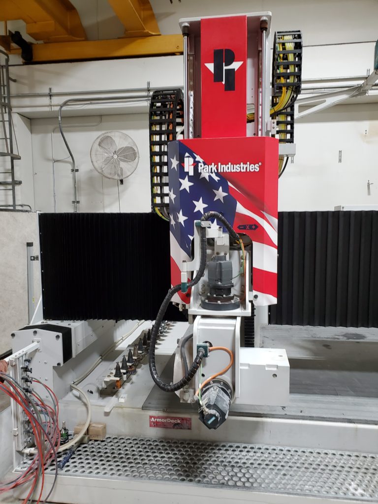
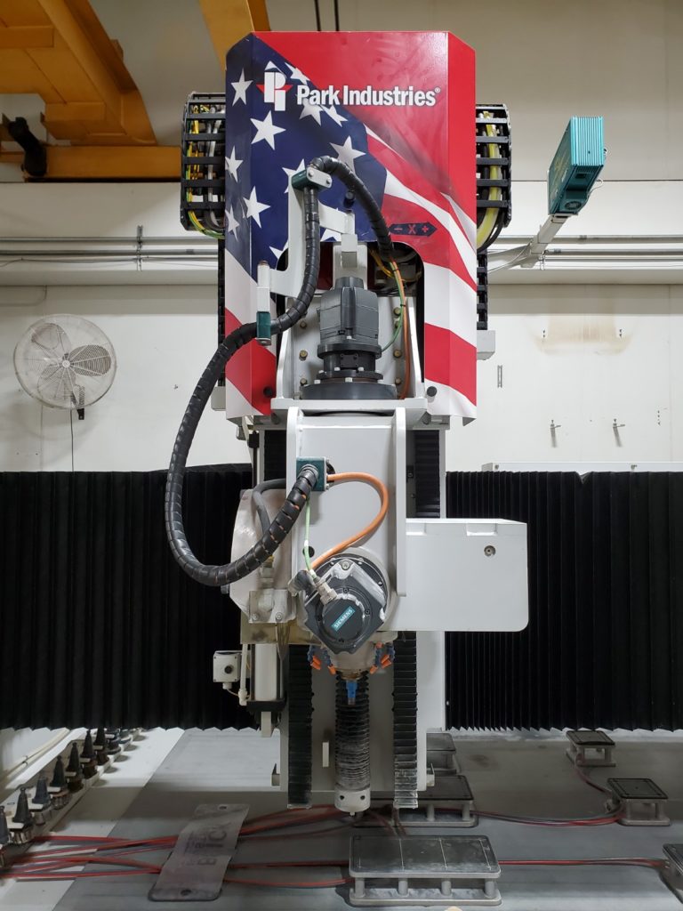
Position the cross travel and gantry. Disconnect the two 1/2″ water lines from the halo.

- Position the cross travel about 36″ away from the left tool rack and the gantry so the arbor is above the front of the table.
- Put the blade up.
- Turn System OFF.

- Unplug the 1/2″ water line from the right side and leave it loose.
- If the water union drain line is cable tied to the halo water line, cut the cable tie off.
- Then unplug the 1/2″ water line from the left side of halo and leave it loose.
Put the blade down. Lock out the machine power disconnect. Turn off air and water.
- Put the blade down.
- Lock out the machine power disconnect.
- Turn off the air and water.

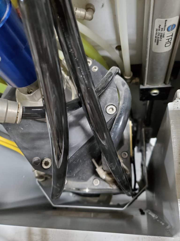
- Remove the back pull cord cable.
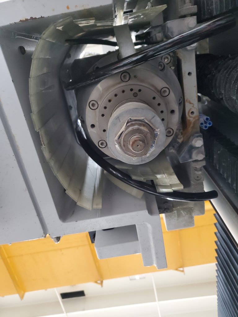
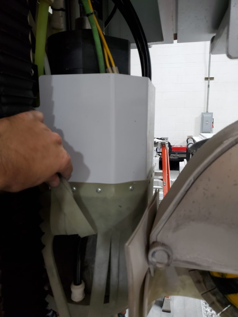
Remove the saw and spindle covers.
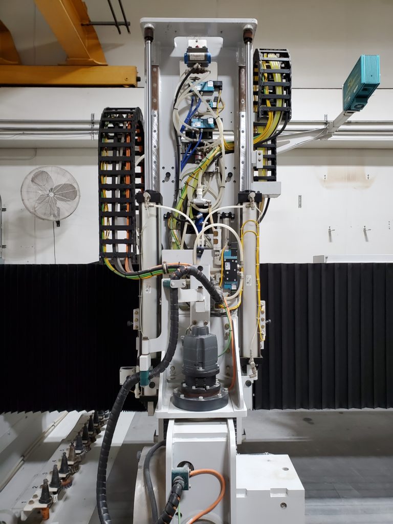
- Remove the blade shroud.
- Then remove the spindle shroud.
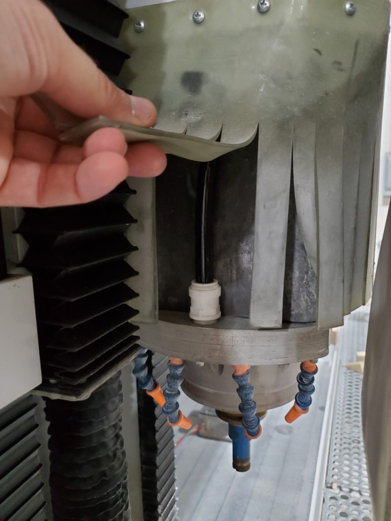
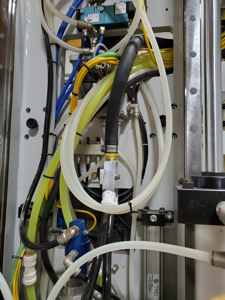
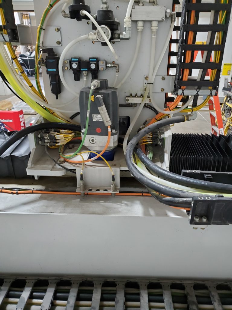
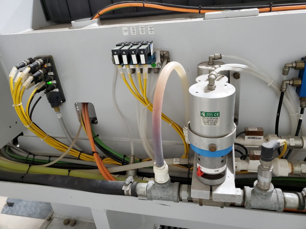
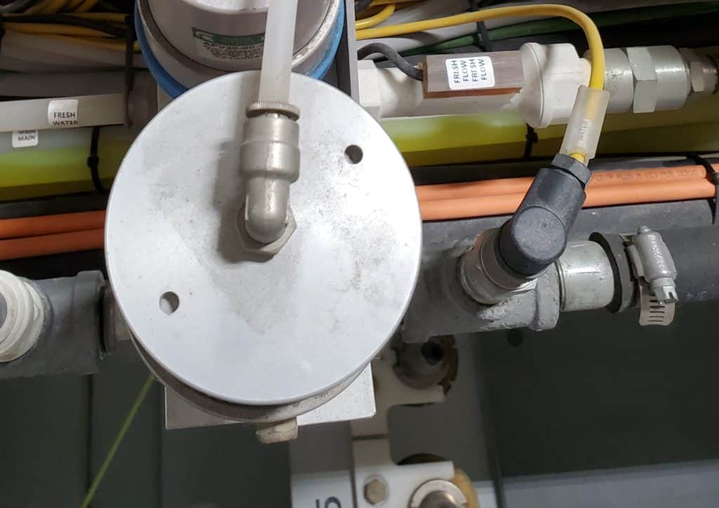
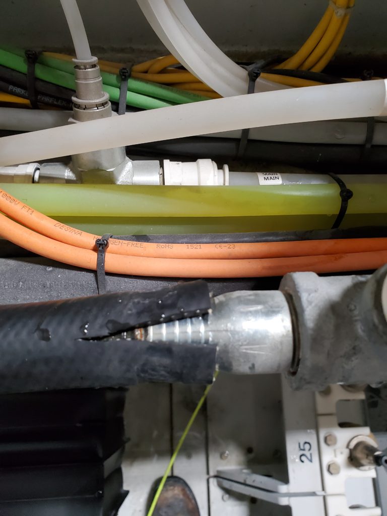
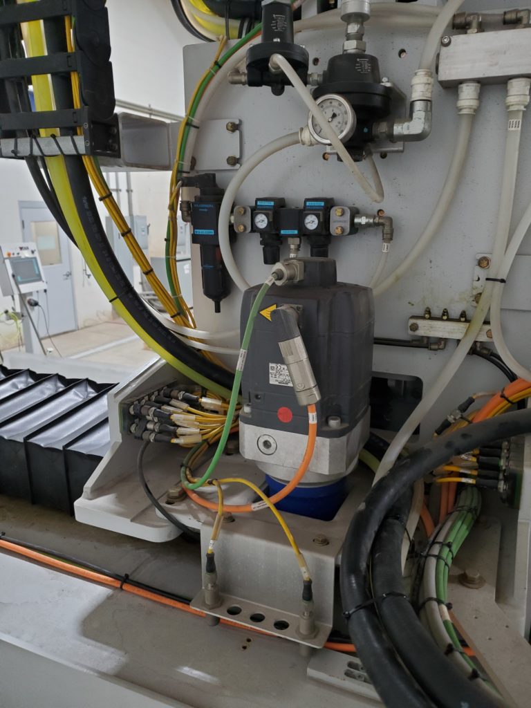
Remove the old Y-block. Install the new Y-block. Cut the 5/8 black water line in half and connect them to the bottom fittings on the new Y-block.
- The Y-block is located right above the water union.
- Pull out the 5/8 clear line from the top fitting and leave it loose for now. Leave the two 1/2″ lines connected that go down to the halo.
- Temporarily unplug any grease lines and air lines that are in the way of the mounting bolt.
- Use a 1/2″ socket to remove the one 5/16 bolt that’s securing the Y-block assembly.
- Lift out the Y-block and 1/2″ halo lines together.
- Mount the new Y-block. Use the new 5/16 bolt and washer if needed.
- Re-connect all grease and air lines that may have been disconnected!
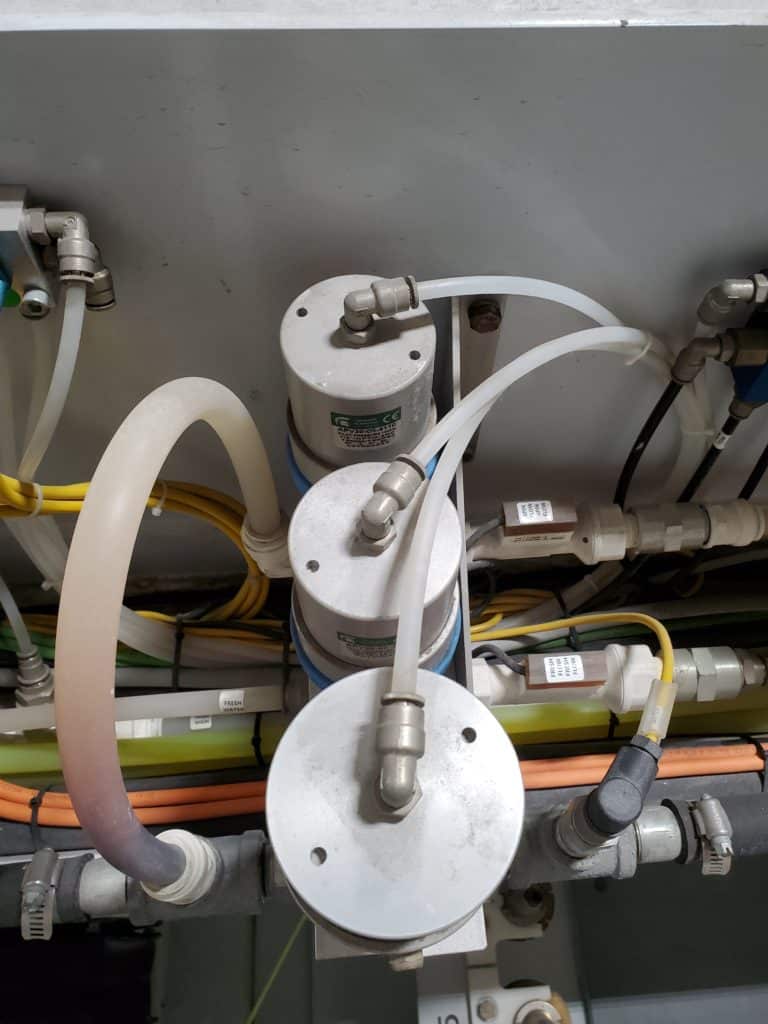
- Take the 5/8 black poly water line and cut it in half so there are two pieces that are the same length.
- Slide them down on the inside of the spindle motor shroud cover.
- Pull them down to the halo and leave them loose for now.
- Make sure they are on the inside of the spindle motor cover.
* Note: the halo is removed for clarity.

- Now plug the two 5/8 water lines into the bottom white fittings on the Y-block.
- Make sure they are pushed in all the way!
* Note: the 3/4 hose will not be connected yet.
Remove the zip ties from the 5/8 recycle water line bundle between the Y-block and the water ball valves. Open up the saw rise and fall cable carrier. Open up some of the sections on the cross travel cable carrier.
- Starting at the Y-block, follow the 5/8 recycle water line back to the water ball valves and use a side cutter to remove the zip ties from the water line bundle.
- Remove the cable ties from the water line bundle.
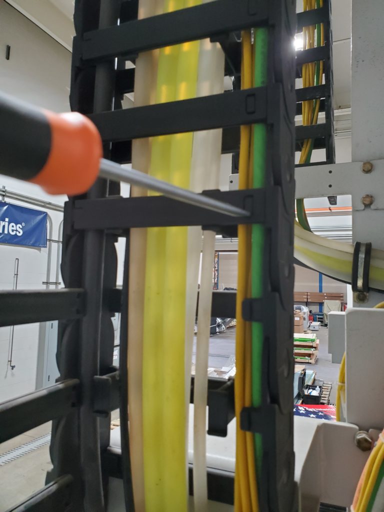
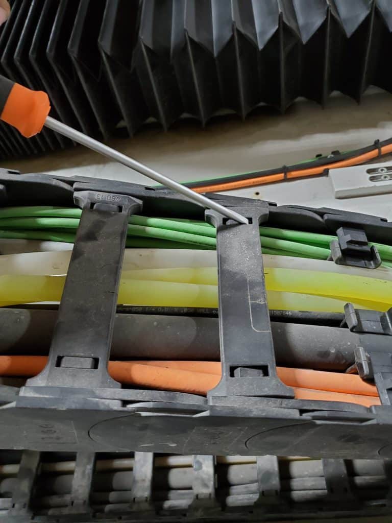
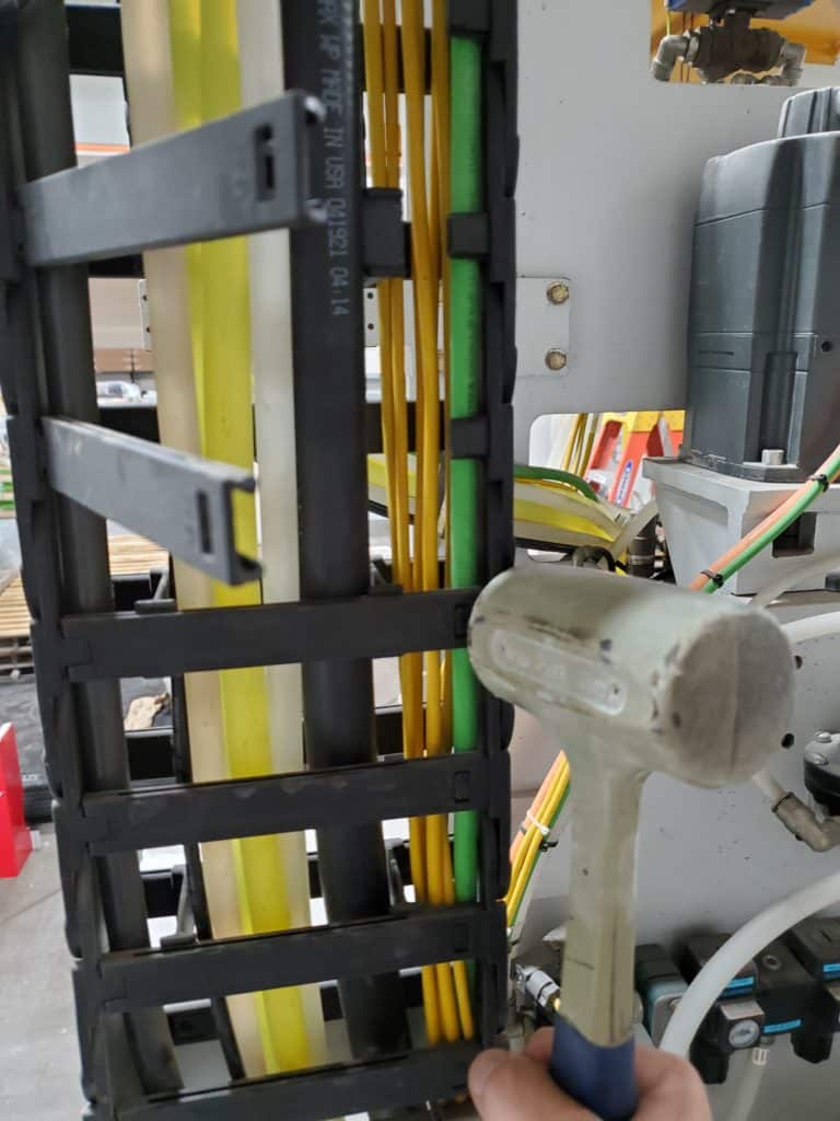
- To make it easier to put the new 3/4 hose in the cable carrier, this step shows how to open up the hinged dividers.
- Use a 3/16 flat blade screwdriver to open the saw rise & fall cable carrier.
* Note: One side is the lock/release and the other side is the hinge.
- To release: push the blade straight into the bottom slot
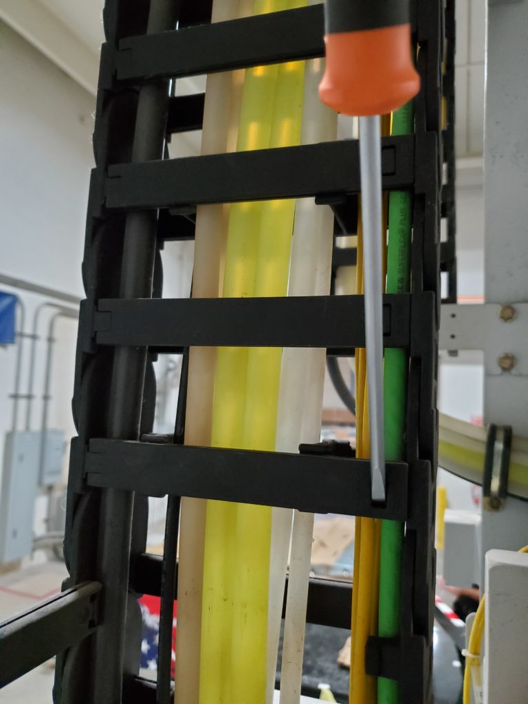
- Then, push the handle up.
- If this doesn’t fully release it, put the screwdriver tip in the adjacent side from where you pried up from and pry the handle down.
- Once released, swing the divider to the side.
* Note: Closing these up is in a later step. - Some of the short vertical supports (pictured to the left of the screwdriver tip) may fall out when removing the clear 5/8 line and installing the 3/4 rubber hose. If any fall out, make sure to put them back in. They simply clip on.
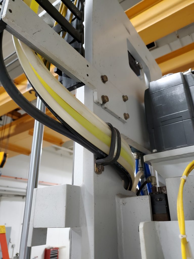
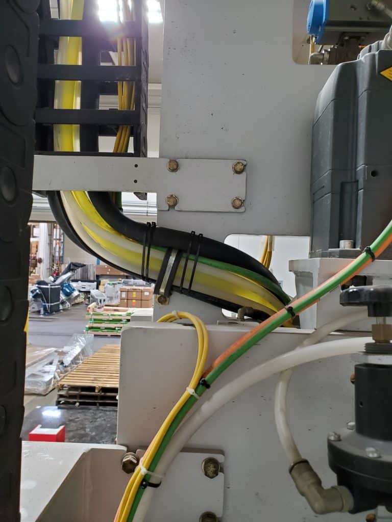
- Keep following the water line bundle behind the cross travel motor to the cable carrier and remove the cable ties.
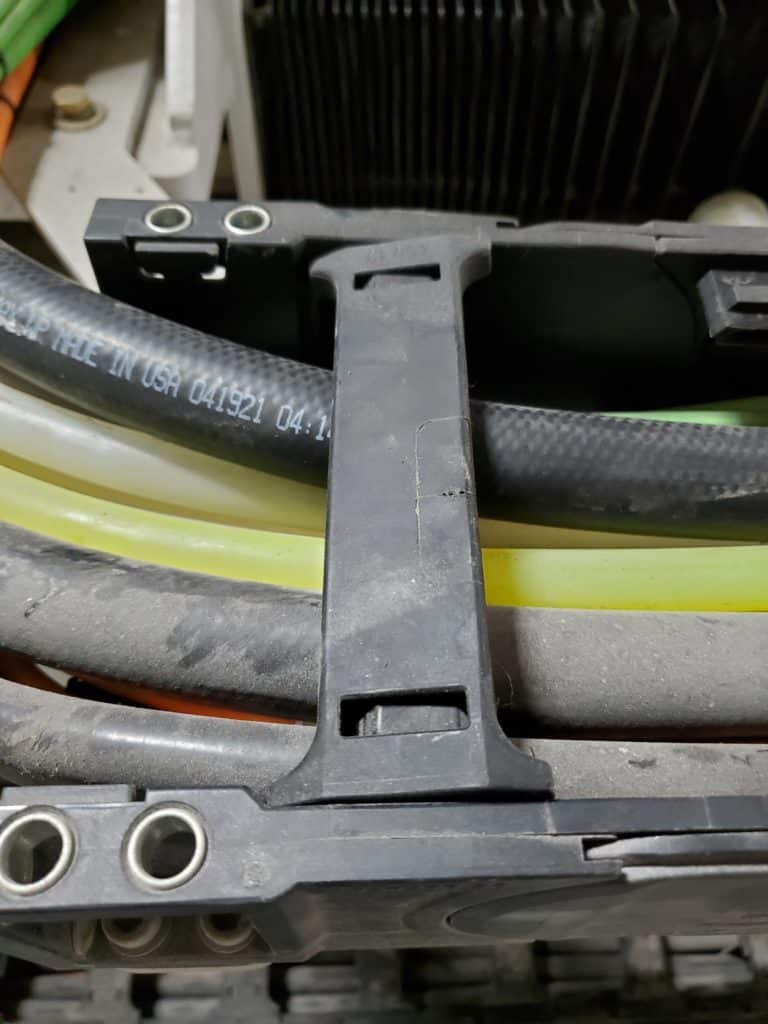
- When you reach the top side of the cross travel cable carrier, you can open part of it up to make it easier to install the 3/4 water hose.
- To remove the cross travel cable carrier supports:
- On one end, push the screwdriver tip straight into one of the slots, then pry the the handle down to pop it loose.
- Then, go to the opposite end and on the same side. Push the tip straight in and pry down to pop it loose.
- Once one whole side is popped up and loose, you can grab it by hand and pull it off.
* Note: Installation is in a later step.
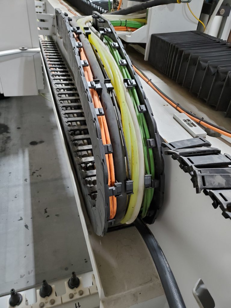
- Remove the top dividers and the ones on the outside of the radius.
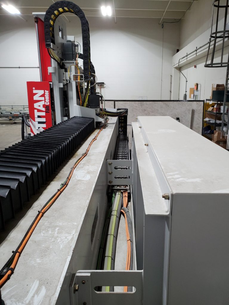
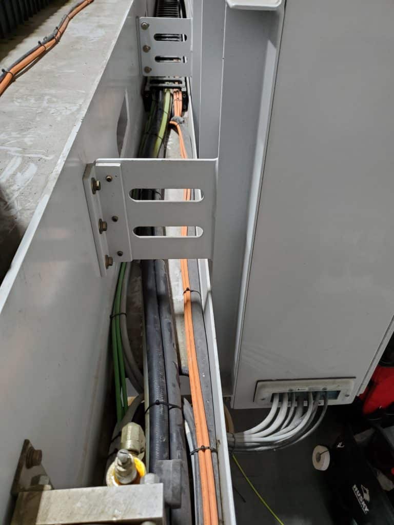
- Continue removing the cable ties from the water line bundle behind the main enclosure.
- Remove the cable ties up to the water ball valves.
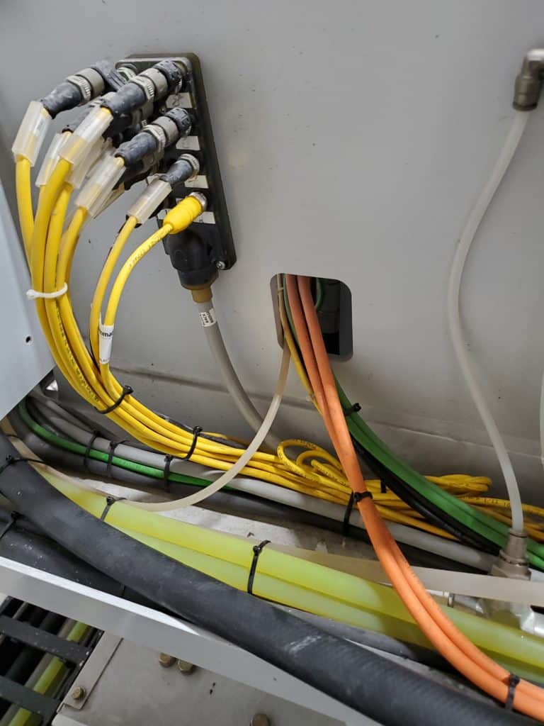
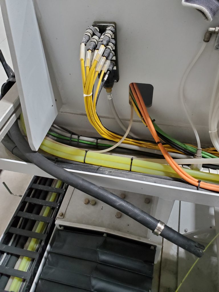
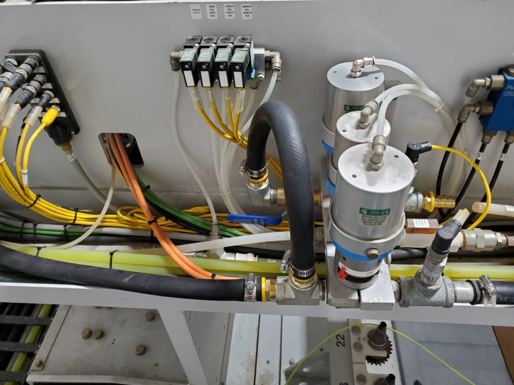
- Then remove the cable ties from the cable bundle between the recycle flow switch and the 8-port I/O block (mounted vertically on the left side and has 8 connection ports on it).
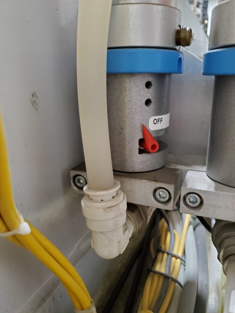
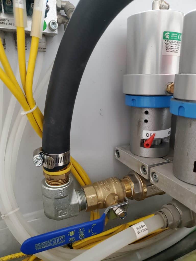
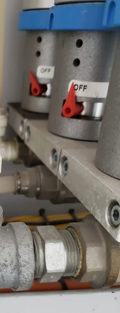
Remove the old recycle water flow ball valve assembly. Remove the old recycle flow switch cable.
- The recycle ball valve assembly is the inside one against the bridge.
- Unplug the 1/4″ air line from the top of the valve.
- Unplug the 5/8 water lines from both sides of the recycle ball valve assembly.
One side jumps from the splitter that’s on the saw water valve and the other one is on the right side of the flow switch.
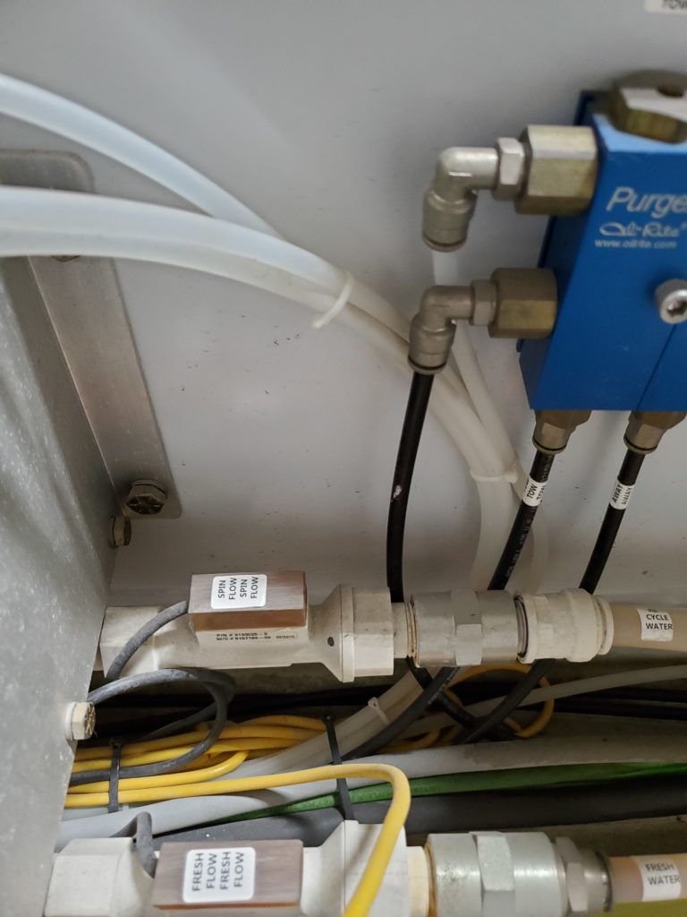
- Find the recycle flow switch cable and follow it back to the 8-port I/O block.
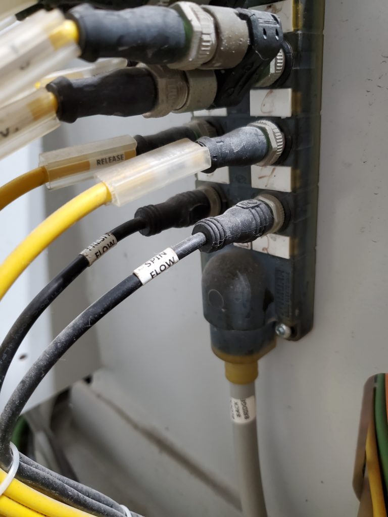
- The recycle flow switch cable is plugged into port 2; the bottom right port. Disconnect it and pull the cable out and back to the flow switch.
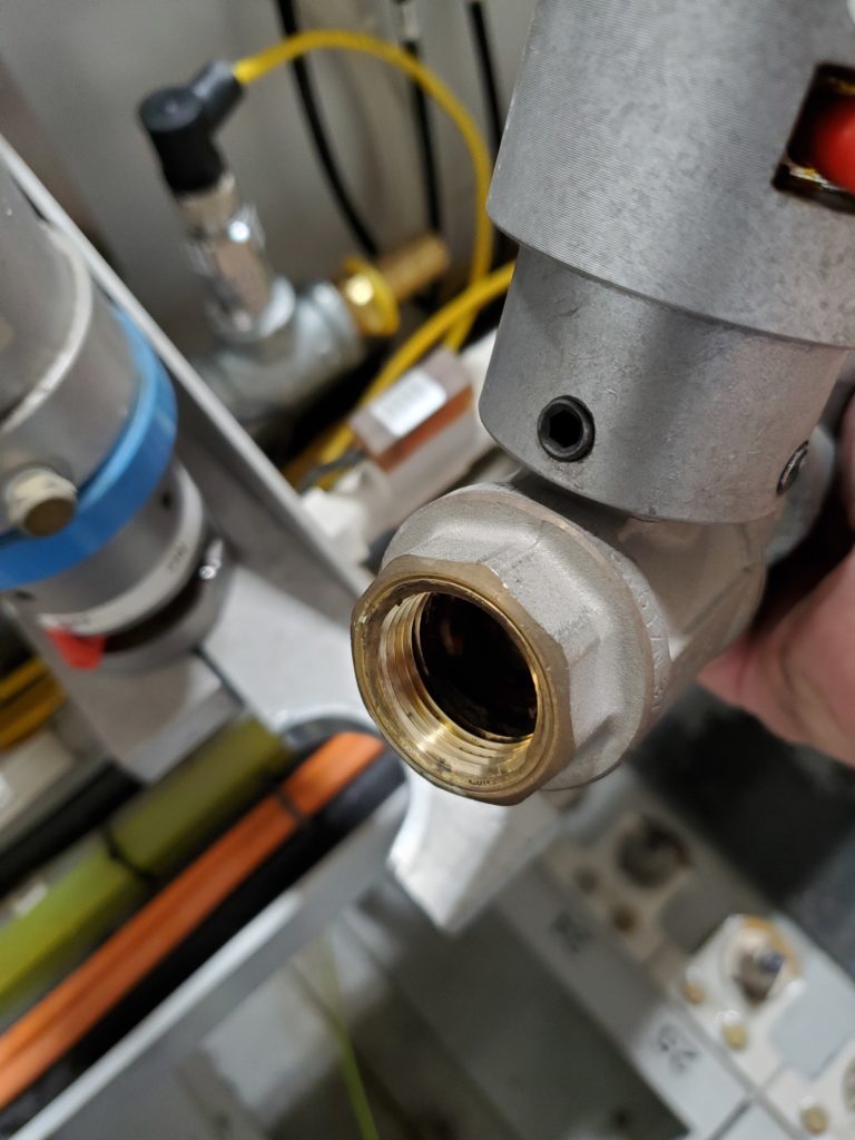
- The recycle water ball valve assembly should be ready for removal. Use a 3/16 Allen wrench to unbolt the mounting cap from the bracket.
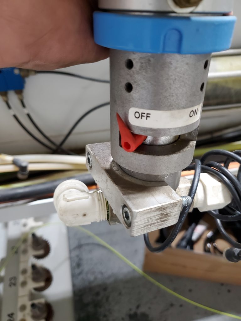
- Use a wrench or channel lock pliers to rotate the 5/8 fitting so that you can remove the mounting cap.
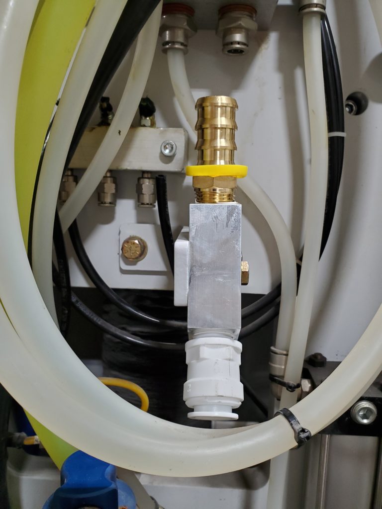
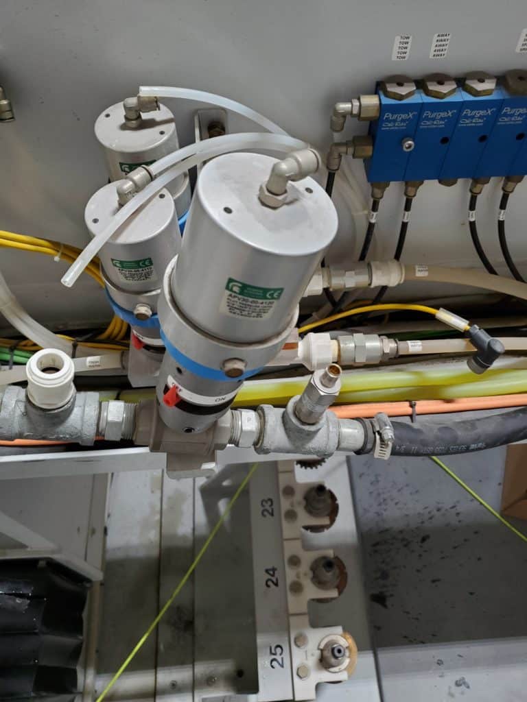
Install the new recycle water ball valve assembly. Install the new recycle flow switch cable.
- Install the new ball valve assembly and tighten the mounting cap down.
- Reconnect the 1/4″ air line into the top of the valve.
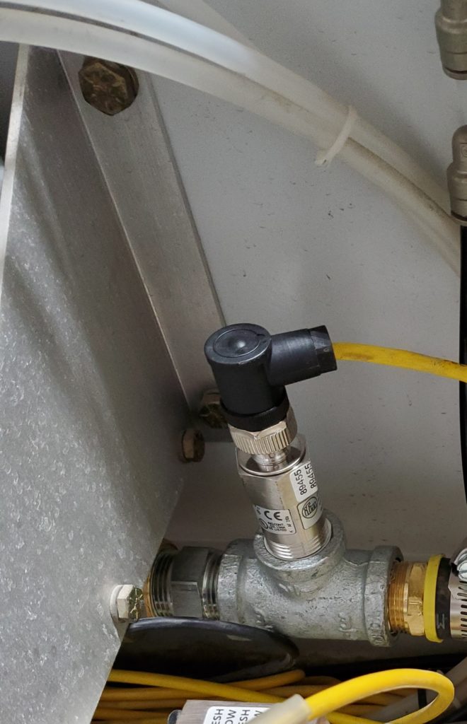
- Connect the new flow switch cable onto the flow switch.
* Note: The connector is keyed and only goes on one way!
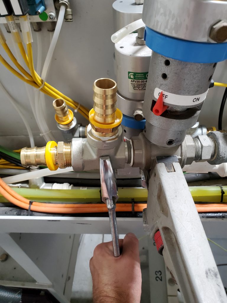
- Open the hand ball valve.
- Pull the cable back to the 8-port I/O block and connect it.
- Use cable ties to bundle the cables back together.
Remove the old water splitter from the saw water ball valve. Install the new water splitter.
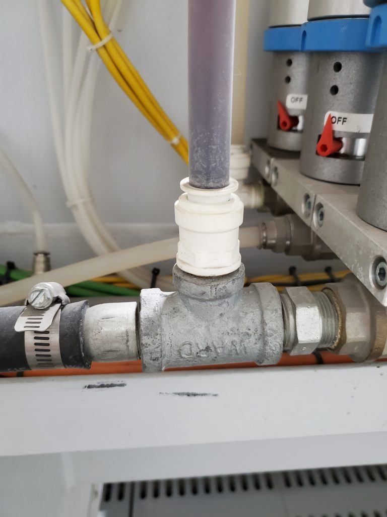
- This is the water splitter on the saw water ball valve that will be replaced.
- In order to take it off and install the new one, the saw ball valve assembly has to be unbolted and pulled away from the bracket.
- Disconnect the air line from the top of the valve.
- Disconnect the flow switch cable from the flow switch.
* Note: Leave the discharge hose connected!
- Use a utility knife to cut through the 3/4″ water line that’s connected to the left side of the water splitter.
- ONLY cut enough to pull the hose off! This hose will be reconnected to the new one and there isn’t much slack!
* Note: Leave the discharge hose connected!
- To get more slack on the hose, cut off the cable ties along the hose all the way back to the gantry cable carrier.
- Then, pull the hose off.
Make sure the hose clamp stays on it.
- Cut the end of the hose off to remove the damaged end that was on the old fitting!
* Note: Leave the outfeed hose connected on the right side of the valve!
- Now you can unbolt the mounting clamp from the saw valve and pull it out of the bracket.
- You can set the valve assembly on top of the mounting bracket to help hold it.
* Note: Leave the outfeed hose connected on the right side of the valve!

- Hold the bottom of the valve with a large crescent wrench or pipe wrench.
Then, use another wrench to turn the water splitter out of the valve body.
- Clean out the threads in the valve body.
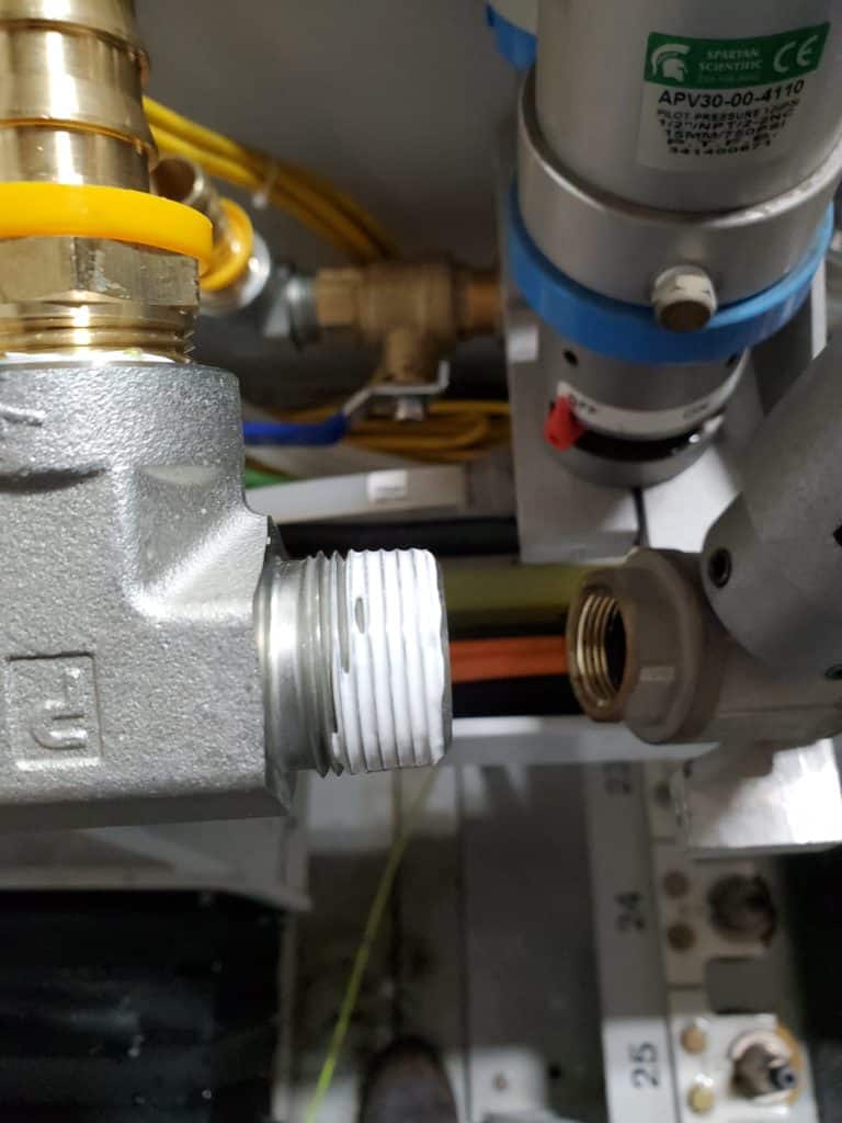
- Apply teflon tape or Loctite 567 thread sealant to the threads on the new water splitter.
- Hold the bottom of the valve body with a pipe wrench.
Turn the water splitter until it’s tight and the top fitting is facing straight up.
- Bolt the ball valve assembly back onto the bracket.
- Make sure the hose clamps are on the hoses before sliding them onto the barbed fittings.
- To aid assembly, put a thin coat of lubricant in the hose and on the barb fitting.
You may have to twist the hose back and forth as you push it on.
- Once the hose is on the fitting all the way, tighten the hose clamps.
Remove the 5/8 clear water line. Install the 3/4 rubber hose.

- Remove this clamp that’s at the bottom of the saw rise & fall cable carrier. It will be reused.
- Starting here, pull the 5/8 recycle water line out of the clamp.
- Put the clamp back on.
- Pull the 5/8 line out of both cable carriers and back to the water ball valve.
- Install the 3/4 hose.
- Start by pushing the hose into the radius of the cross travel cable carrier and towards the water ball valve.
- Pull it to the ball valve.
- Make sure the hose clamp is on the hose, then connect the hose to the barb fitting.
- Tighten the hose clamp.
- Secure the water line bundle with cable ties behind the main enclosure and to the cable carrier.

- Now route the 3/4 hose in the top side of the cross travel cable carrier.
- Reinstall the cross travel cable carrier supports:
- First, slightly tilt the piece and push it against one side.
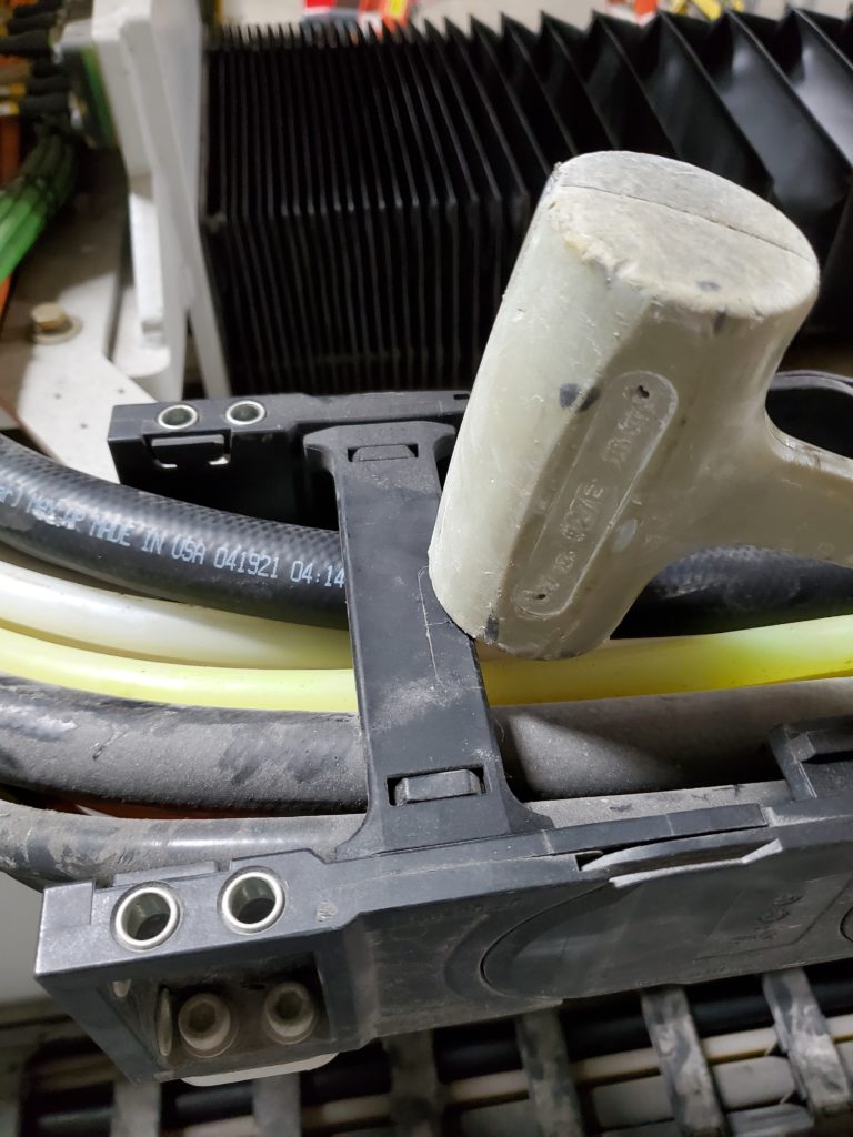
- Then, tap the other side down with a soft dead blow hammer.
- Reinstall all of the supports that were removed.
- Route the hose behind the cross travel motor.
- Use cable ties to secure it to the water and air line bundle.
- Put the 3/4 hose in the saw rise & fall cable carrier.
- To close the hinged supports:
- Close them so they’re against the tab, then tap them into place with the dead blow hammer.
* Note: Make sure to reinstall any vertical dividers that may have fallen out.
- Route the water hose on top of the other lines. Secure it with multiple cable ties.
- Make sure nothing by the clamp is sticking out past the arbor up/down proximity switches.
- If necessary, use the dead blow hammer to tap the clamp flatter.

- Hold the 3/4 hose beside the barbed fitting on the Y-block and mark where it should be cut.
Cut it to length.
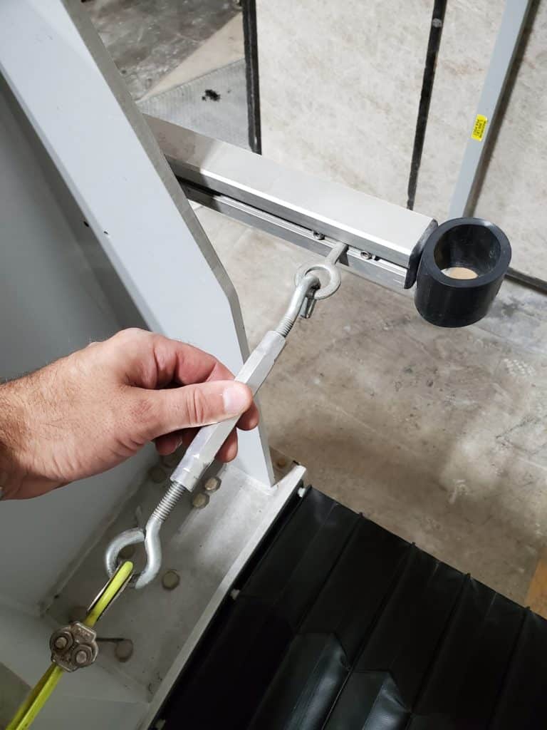
- Reinstall the back pull cord cable.
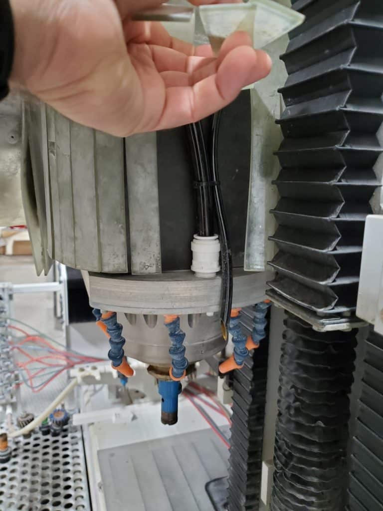
Power up. Raise blade up. Replace the two 1/2″ fittings on the halo with two 5/8″ fittings.

- This step is raising the blade to gain better access to the halo.
- Power the machine on.
- Turn the supply air on.
- Open the Park front end and
raise the blade UP.
- Power back down and turn the air off.
* Note: Leave the shrouds off for now.
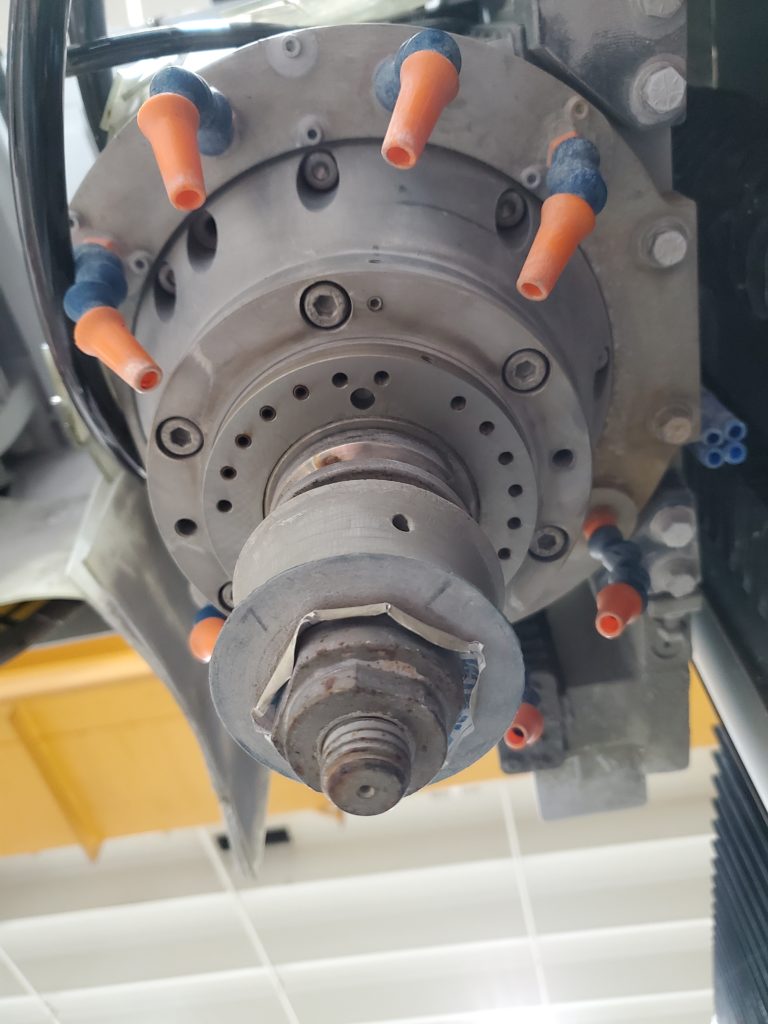
- The halo ring is mounted with two 5/16 bolts that are on the side with a flat edge. These bolts will be reused.
- Use a 1/2″ socket and remove the two bolts.
* Note: There may be two flat washers acting as spacers between the halo and the spindle assembly. Gently pull the halo straight down and look for these spacer washers.
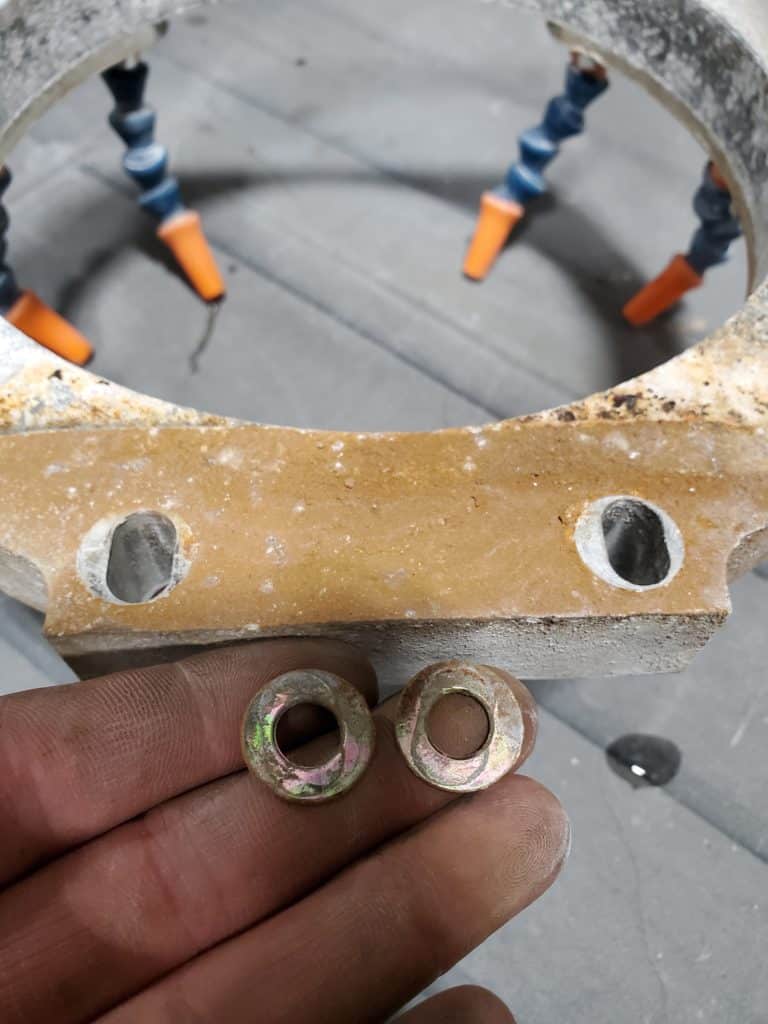
- If there are two spacer washers, they will be reused.
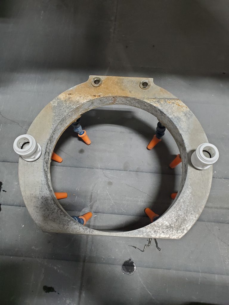
- Clean off the mating surface of the halo and where it mounts to the spindle assembly with a Scotch-brite pad or equivalent.
- Use a crescent wrench or adjustable channel lock pliers to remove the two 1/2″ fittings.
- Clean out the threaded holes in the halo as much as possible.
- Use teflon tape or equivalent sealant on the threads of the two 5/8 fittings.
Install the new 5/8 fittings.
* Note: The 5/8 fittings might not screw in all the way if there is build up in the threads, so only turn them in until they stop.
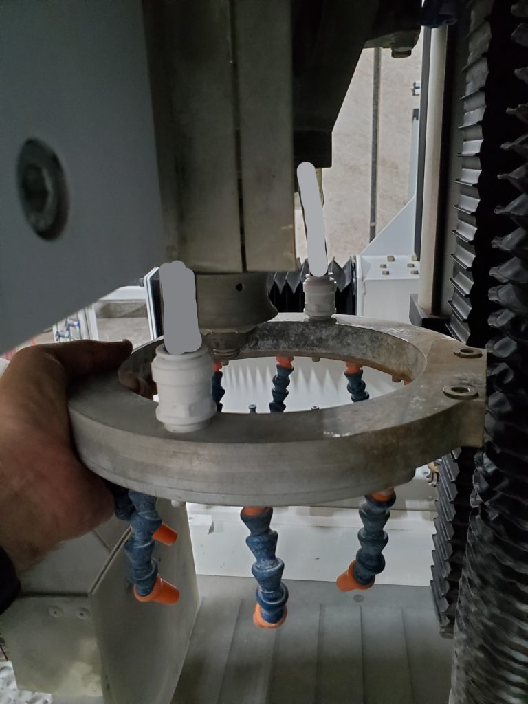
- Put the 2 spacer washers back on top of the two bolt holes and lift the halo back up to the mounting surface.
- Bolt it back into place with the two 5/16 bolts.
- The two 5/8 black water lines can be cut to length and connected to the two halo fittings (left side shown).
- Start on one side; grab and hold one of the lines with your hand and put it beside the fitting.
As you do this, push up on the hose to create some slack.
- Look at the lines above the top of the shroud and make sure that they are not pulled tight against the spindle motor.
- After verifying that the hose isn’t pulled tight, hold it beside the fitting and use the hose cutter to cut the hose straight.
- Then, push it into the fitting and make sure it’s pushed in all the way.
- Go to the other side and repeat the procedure.
- Before you cut the 5/8 line, make sure it’s not pulled tight!
- After it’s pushed in all the way, zip tie the 1/4″ drain line that comes down from the water union to it.
Power the machine back on. Turn air and water on. Check for leaks. Put the shrouds back on.

- Power up the machine.
- Turn on air and water.
- Bring the blade down.
- Manually start the spindle in the manual screen to verify that the water ball valves turn on.
If necessary, use the hand-operated shutoff valve on the recycle ball valve to adjust the halo water flow.
- While the spindle is running, check for water leaks at the halo, Y-block, and the saw water and recycle water ball valve assemblies.

- Lower the blade if it’s not down.
- Power down.
- First, put the spindle rise & fall shroud on.
- Then, put the saw rise & fall shroud on.
- Power up.
- Turn the air and water are on.
- Raise the blade up.