
introduction:
For this upgrade, two 3/4″ water lines are required: one for the halo recycled water and one for the spindle fresh water. Water flow results depend on water supply. The optimal set up would be a 4″ main with two 1″ drops; one for recycled and one for fresh water.
Scan to Read on Device:

see step 18 for spindle center water flow kit
Parts list for kit 98750 – Spindle Water Ring.
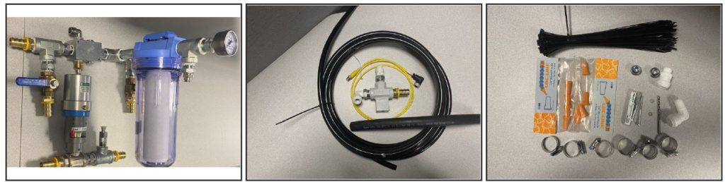
- Main water manifold
- 3/4″ ball valve assembly
- Tee bracket, 20 feet 5/8″ black line, 70 feet 3/4″ ID rubber hose, yellow flow switch cable.
- Black tie straps, 8 1/4″ lock line tips, 6 hose clamps.
- 1 90 degrees 5/8″ fitting, 1 straight 5/8″ fitting, 2 1/2″ NPT plugs.
- No. 21 drill bit, 10-32 tap, 2 10-32 X 2 1/2″ bolts and 2 10-32 lock washers.
Tools needed
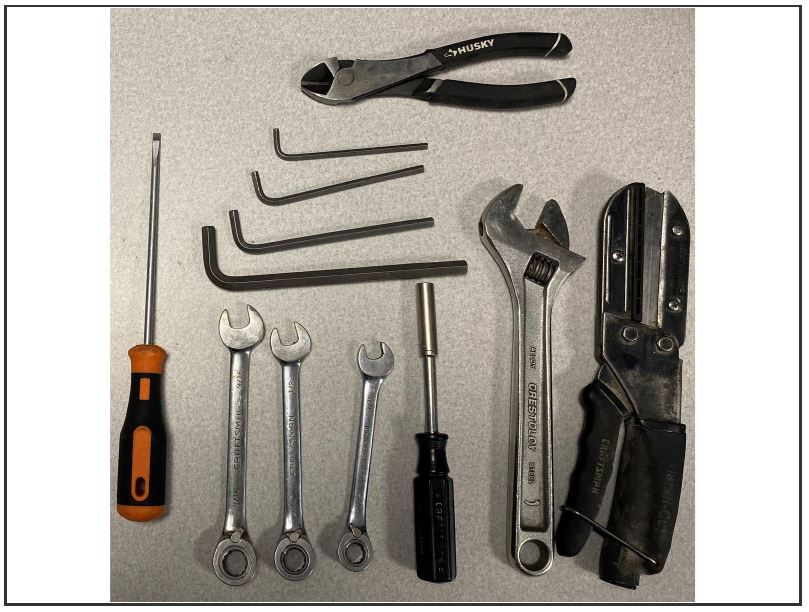
- Flat blade screw driver 3/16″ tip
- Side cutter
- 10″ adjustable wrench
- Hose cutter
- 5/16″ nut driver
- 3 wrenches 1/4″, 1/2″, 9/16″
- 4 Allen wrenches 3/16″, 5/32″, 1/4″,and 3/8″
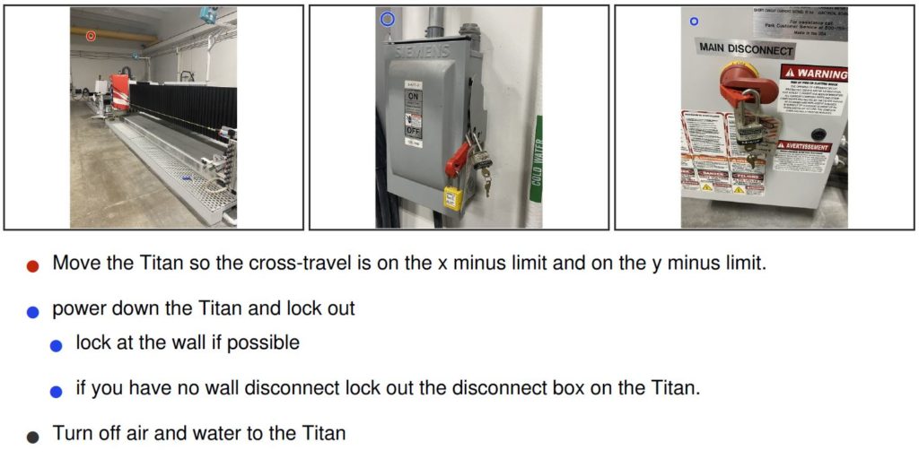
Machine Lockout
Mounting the main water manifold on Titan 2000 Series Machines
- Locate the manifold on the right side of the Titan base.
- Remove the five lines going to the existing manifold.

- Remove the old manifold held in place by 2 10-32″ bolts.
- Mount the new manifold in the same location. New bolts are included in the kit if needed.
Mounting main water manifold for Titan 1000 series
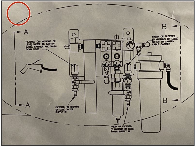
- If your Titan has the older style water manifold (See picture above) the mounting holes for the new manifold need to be added.
- Using the aluminum block on the new manifold make a template and mark the holes on the base.
- Find a spot on the base that is close to the existing water lines.
- Mark the holes with the template and drill the 2 mounting holes using the supplies No. 21 drill bit.
- Tap the holes with 10-32 tap that came with the new kit.
- Mount the new water manifold.
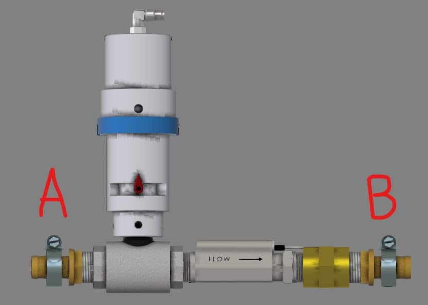
Connect the water lines to the new manifold.
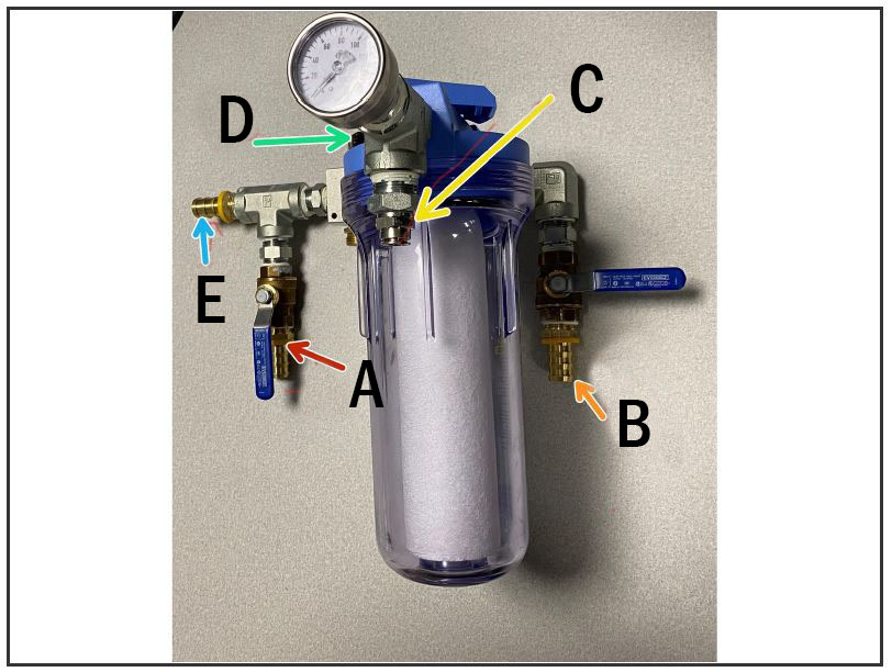
- A = incoming recycled water (new line)
- B = incoming fresh water (new line)
- C = fresh water going to spindle (existing line)
*Note: if the spindle fresh water kit is being installed, this line will get replaced - D = liquid ring vacuum pump (existing line) If your machine doesn’t have liquid ring vacuum pump remove fitting and install plug with 1/2″ NPT.
- E = recycled water going to the halo. Wait to connect this line.
Valve upgrade for 1000 series 1016 or older.

- A ball valve upgrade it is needed if you have this style water valve bank.
- Upgrade kit part number 99372.

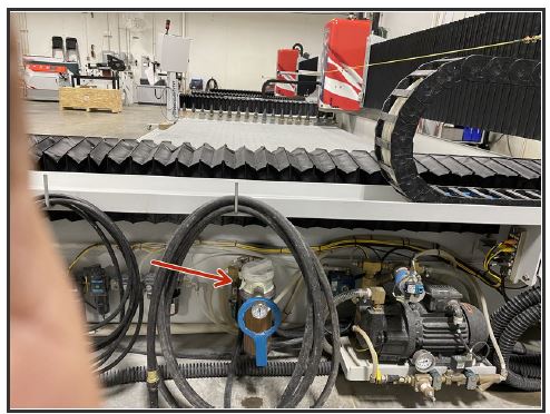
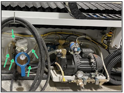
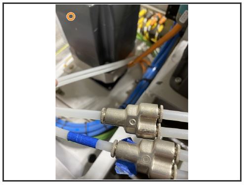
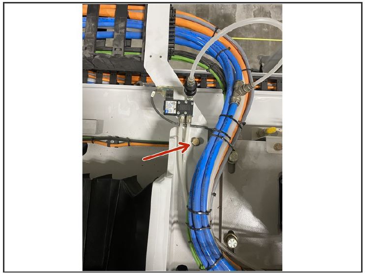
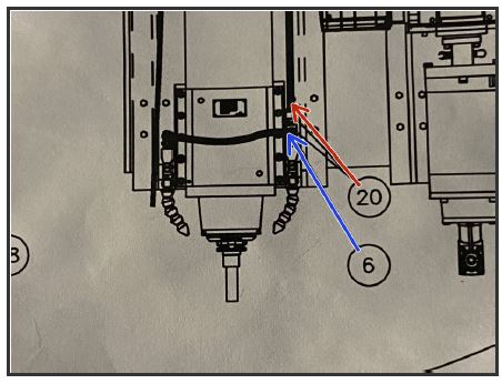
Remove the 1/2″ recycled water valve
- Remove the two 5/8″ water lines (red arrows)
- Remove the 1/4″ air line from the top of air valve (orange arrow)
- Find the flow switch cable for the recycled water and cut the tie straps that hold the cable.

- Remove the cable from the 8 port block.
- Depending on your machine model the cable could be in a different place.
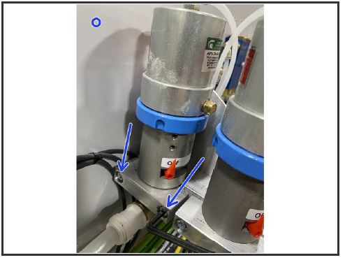
- Remove the 2 bolts that hold the valve in the bracket. Uses a 3/16″ allen wrench.
Installing the new 3/4″ water valve
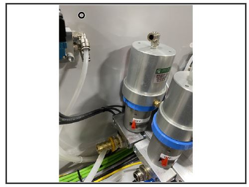
- With the old valve removed, the new 3/4″ water valve will go in it’s spot.
- Mount the new valve using the mounting hardware removed in the previous step.
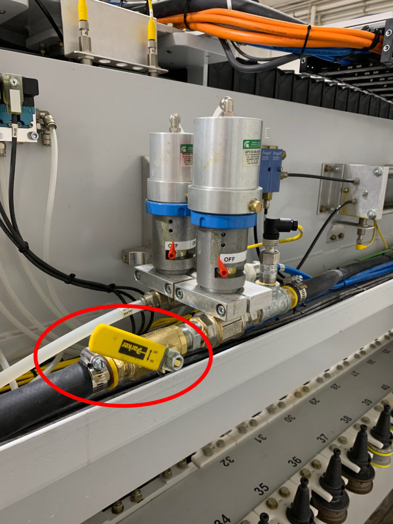
- Note: the new ball valve will also come with a manual on/off valve where you can reduce water flow if necessary.
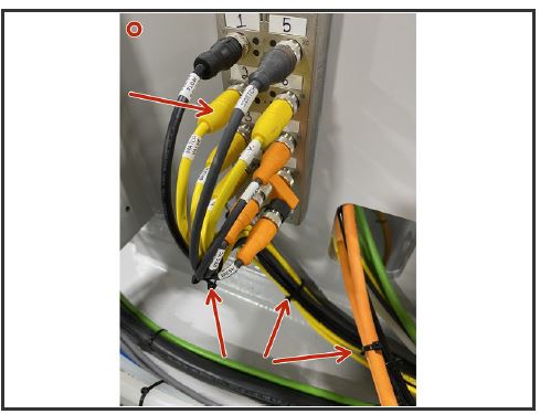
- Plug in the new flow switch cable in the 8 port block where the old one was removed from.
- Using the tie straps, bundle the new cable with the old ones and tie it back.
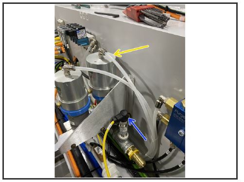
- Plug the cable into the new flow switch
- Plug the 1/4″ air line in to the top of valve.
- The new water line will be installed later.
Remove the front shroud
- Disconnect front pull cord
- If you have a water curtain, disconnect air lines.
- Remove the spindle shroud
Remove the Z Axis cable carrier covers
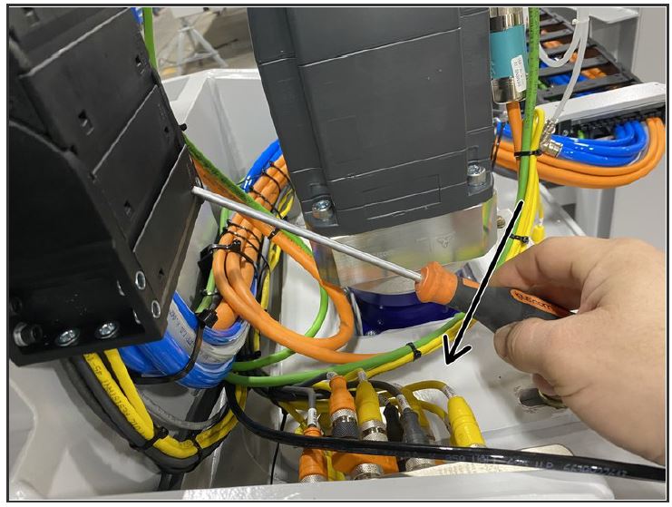
- Remove the covers using a flat blade screw driver.
- Start on the side with the X Axis motor.
- Insert the screw driver and pry in the direction of the arrow, you will feel a little pop and cover should be free.
- Some of the Titan 1000’s series have tabs on the side to remove the covers.
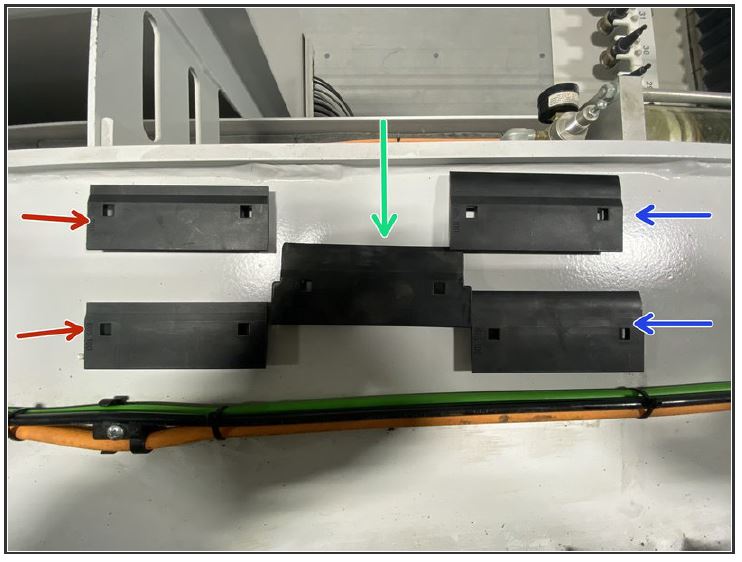
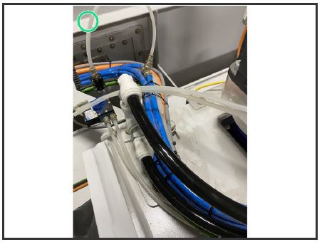
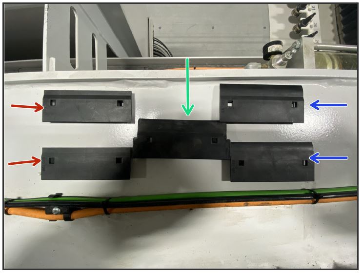
There are 3 different covers on the carrier:
- Red arrow – Cover for the back side of cable carrier by cross travel motor
- Blue arrow – are for the spindle side.
- Green arrow – is for the middle of the cable carrier.
Mounting the Tee-Bracket 2000 Series Titan

- The old tee bracket is located on the right side of the spindle towards the bottom.
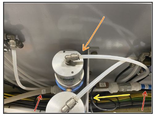
- Remove the three lines with the red arrow that go into the tee bracket.
- There is one bolt that holds the tee bracket to the Titan. Use 9/16″ wrench to remove.
- Remove the tie straps so you can pull back the 5/8″ supply line back to the cross travel cable.
- Mount the new tee bracket in the same location using existing bolt.
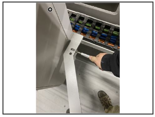
Mounting the tee bracket on 1000 Series Titan
- On the bracket where the cross-travel cable carrier attaches remove the bolt closest to the cable carrier 9/16″ wrench.
- Attach the new bracket using the same bolt.

- The two 5/8″ fittings need to be changed so the 90 degree fitting is on top.
Halo on the Series 2000 Titan
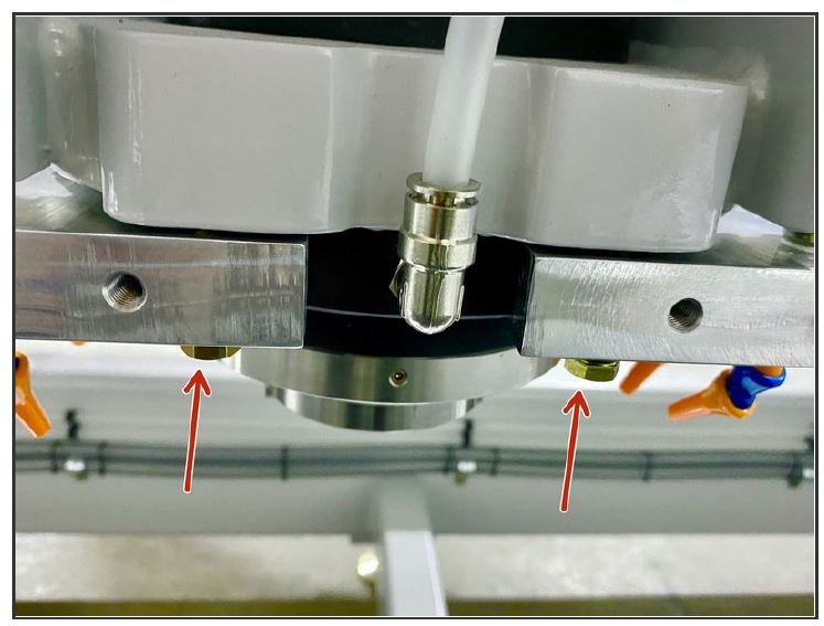
- Remove the two bolts that hold the halo ring.
- Use 1/2″ wrench
- May need rubber mallet to get the halo ring off.
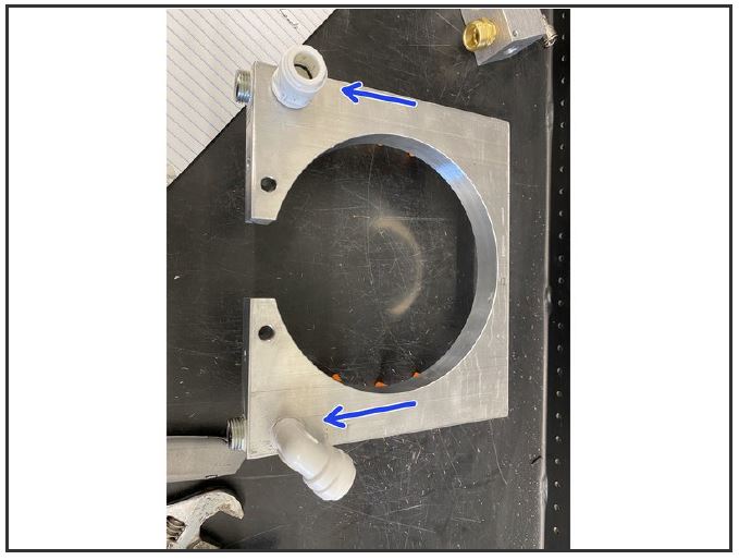
- Remove the 1/2″ fittings and install the new 5/8″ fittings.
Installing new tips on Halo 2000 Titan Series

- Grasp the blue portion on the lock line with a pliers and pry the tip away from the pliers.
- Remove all 8 tips.
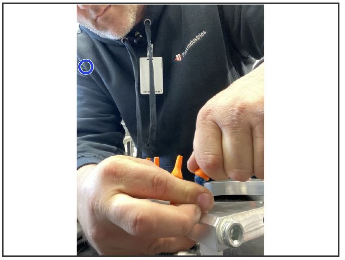
- Install the new tips. Grasp the blue portion of the lock line with one hand to keep the line from moving, push the new tips on.
- Use a side to side motion to get the tips on.
Modifying Lock line manifold on 1000 Series Titan
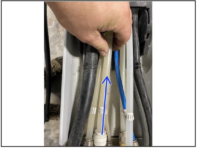
- Remove the 5/8″ supply line. Pull this line back to the cross travel by cutting the tie straps that hold it in the water line bundle.
- Remove the line and fitting from position 6. Install one of the 1/2″ NPT plugs where you took the fitting out.
- Apply thread sealant to plug and use 3/8″ Allen wrench.

- Cut the 5/8″ line that came in the kit into 2 equal lengths. Attach one line to each of the lock line manifolds.
- Use the tie straps to bundle the 2 5/8″ lines back to the Tee Bracket on the back side of the cross travel.
- Attach the lines to the tee bracket.
Remove all 5/8″ recycled water lines

- All the 5/8″ recycled water line is going to be replaced by 3/4″ rubber hose.
- There are 3 sections of line that need to be removed.
- First Line is the line that runs from old main water to the gantry tray manifold.
- Second line runs from gantry tray manifold through gantry cable carrier to the old ball valve.
- The third line runs from the old ball valve through cross travel cable carrier to the spindle.
Center Spindle High Flow Kit 98751 Install

- Cut the rubber hose so you have a 30 foot and 40 foot piece.
- Connect one end of the 30 foot piece to point E on the main water manifold using one of the hose clamps. The hose fits tight to the barb, you can apply a little soap and water to help.

- Run the 3/4″ line with the other lines over to the end of the gantry cable carrier trough. Secure it to the other lines using tie straps.
- At the end of the trough the 3/4″ line will not go into the manifold. Instead make a curve before going into the gantry cable carrier.

- Run the 30 foot line through the gantry cable carrier to the new ball valve. Connect the other end of the hose to point A on the ball valve.
- Use a hose clamp to secure it to the barb.
Running the 3/4″ hose to spindle.
- Attach one end of the 40 foot piece to point B of the new ball valve.

- Run the line down the trough on the back side of the bridge and through the cross travel cable carrier.
- The line is a tight fit into the cable carrier you may need a second person to help.
- The dividers in the carrier may need to be adjusted to fit the 3/4″ hose.
- Bundle the 3/4 hose with all the other water and air lines and secure them with tie straps.
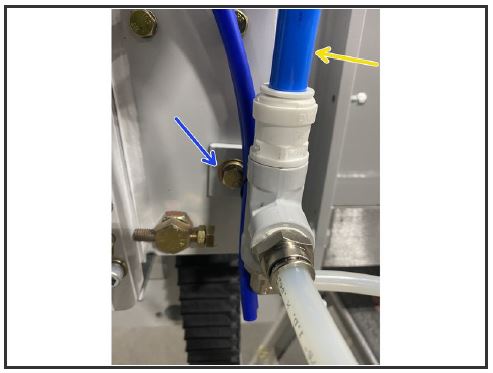
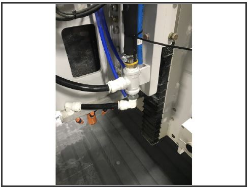
- Attach the other end to the hose barb on the reducer assembly. You will want to place this somewhere out of the X axis cable carrier and where it won’t get pinched or damaged.
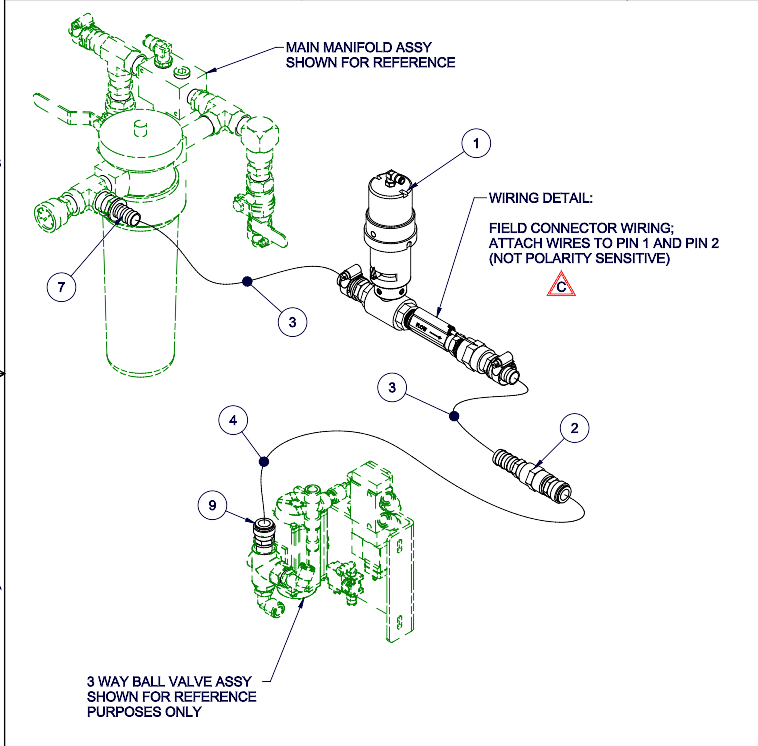
- Run the 5/8″ water line from the reducer to the top of the 3 Way Valve as pictured in item #9 here.
Make sure all the lines that were installed are secure in a way that they will not get damaged while operating the Titan.
Z Axis Cable Carrier
Once all the lines are secure the covers can go back on the Z Axis cable carrier.
- Red arrow – Cover for the back side of cable carrier by cross travel motor
- Blue arrow – are for the spindle side.
- Green arrow – is for the middle of the cable carrier.
Covers overlap each other, start from the spindle side.
Covers on 2000 Series tilt into place.
Check for leaks
- Check all the hose clamps are tight and all lines seated in the fittings
- Attach the pull cord
- Turn on the water and air
- Power up the Titan
- Go to manual screen then turn on the spindle. You may need to start a couple times due to air in lines.
- While spindle is running look over all connection points for leaks.
- Reconnect the air lines for the water curtain.