Upgrade instructions for converting a Wizard into a Wizard Deluxe by incorporating a High Speed Spindle and Drive.
Scan to Read on Device:

Installation time: Approximately 1 day. Familiarize yourself with the Machine components and Schematics found in this document.
Safety First!

Lock-Out and Tag-Out the machine that you will be
working on and notify others before you begin. You will need to disconnect the electrical, air and water supplies to this machine.
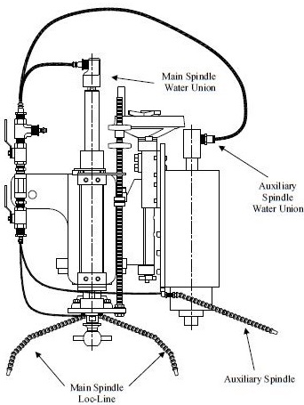
This side view shows the High Speed Auxiliary Spindle on the right hand side of the drawing
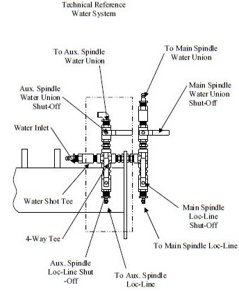
This side view shows the Manually operated Ball Valves plumbed together to for directing water flow to the Main Spindle or High Speed Spindle.
Tools and Supplies Required
Wrenches
4 mm hex wrench
6 mm hex wrench
3/8-inch hex wrench
7/16-inch hex wrench
1/2-inch hex wrench
9/16-inch hex wrench
11/16-inch hex wrench
3/4-inch hex wrench
7/8-inch hex wrench
15/16-inch hex wrench
Miscellaneous
Level
Electric drill
Tapping oil
Utility knife
Medium flat screwdriver
Small flat screwdriver
Slip joint pliers
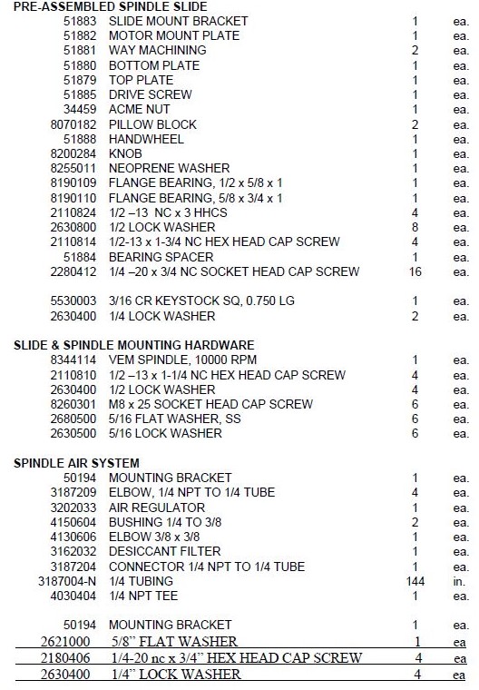
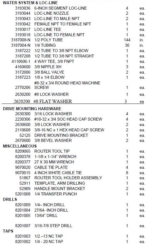
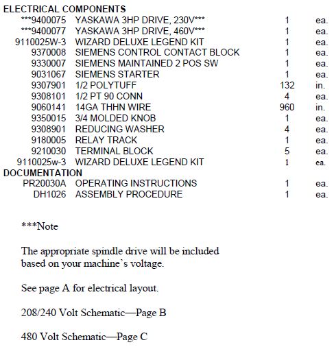
*NOTE: THIS STEP IS TO BE DONE ONLY IF HANDLE INTERFERES WITH THE R&F
Measure and record the distance from the handle to the floor (fig # 1.1). Remove the handle from the
bracket and remove the bracket. Insert the new bracket (fig #1.2) using the existing hardware. This
bracket allows adjustment for clearing the spindle slide attachment. Replace the handle and position to
the prerecorded distance from the floor. Using the holes in the handle as a guide drill a 1/4 hole through
the handle bracket (fig # 1.3). Install and tighten the existing hardware.
Use the supplied template to locate the holes for mounting the spindle assembly. To begin, measure the overall length of the belt guard. This distance will be used to properly position the template. If the belt guard length is 18-1/2 inches , position the template so that the notched corner of the template rests against the bottom and side of the motor mount plate Fig # 1.4).
The distance from the backside of the cylinder mount plate to the front edge of the template will be approximately 7 5/8 inches.
If the belt guard length is 31 inches, position the template 8 1/4 inches from the backside of the cylinder mount plate to the front edge of the template (Fig. # 1.4). The bottom of the template should be located 1/2” above the bottom of the Wizard arm.
Use masking tape to hold the template in the correct position and mark the hole locations with the 1/4” transfer punch.
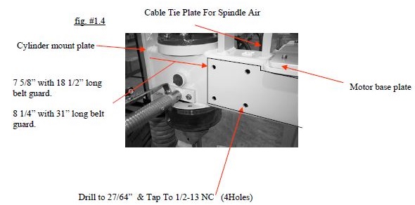
Remove the template and drill all six holes with a 13/64” pilot drill. Drill the 4 holes closest to the front of the machine with a 27/64” and tap to 1/2-13 NC.
Tap the two smaller holes with a 1/4-20 tap. Fasten a cable tie plate on the rear belt cover mountfacing
the front of the machine. This cable tie plate will be used for the spindle air line (Fig. # 1.4).
MECHANICAL ASSEMBLY
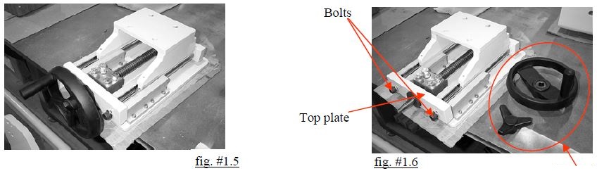
The spindle slide assembly is pre-assembled at Park Industries. In order to mount the slide
to your machine the slide needs to be disassembled. Place the assembled slide on a suitable
workbench, with the spindle mounting plate facing down, allowing the hand wheel to hang
off the table (fig. #1.5)
Slide Disassembly
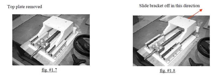
Unscrew the locking knob, slide the hand wheel off of the shaft. Remove the key from the
keyway. Remove the bolts holding the top plate to the assembly (fig. #1.6). Remove the
rubber washer and the top plate (fig #1.7). By using even pressure slide the bracket straight
off of the shafting. The bracket will bind if it is not slid off straight (fig. #1.8).
MECHANICAL ASSEMBLY—cont.
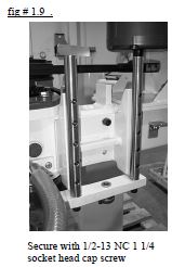
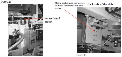
Using the 1/2-13 x 1 1/4” bolts, snug the bracket up to the machine (Fig. #1.9). With the bracket mounted to the machine, slide the spindle plate back onto the slide shafting. Pay close attention to make sure the lead screw seats fully into the bore on the bottom of the bracket (Fig # 1.10). Reattach the top plate and snug, don’t fully tighten the cap screws then replace the handwheel and key. Crank the handwheel up and down a few times to realign the plate’s bearings to the shafting. Periodically snug up the cap screws a little more with each cycle. After a few repetitions, remove the handwheel and key and fully tighten
the cap screws.
MECHANICAL ASSEMBLY—cont.
Using the 1/2-13 x 1 1/4” bolts, snug the bracket up to the machine (Fig. #1.9). With the bracket mounted to the machine, slide the spindle plate back onto the slide shafting. Pay close attention to make sure the lead screw seats fully into the bore on the bottom of the bracket (Fig # 1.10). Reattach the top plate and snug, don’t fully tighten the cap screws then replace the handwheel and key. Crank the handwheel up and down a few times to realign the plate’s bearings to the shafting. Periodically snug up the cap screws a little more with each cycle. After a few repetitions, remove the handwheel and key and fully tighten
the cap screws.
Apply a generous amount of anti-sieze on the screw shaft and replace the rubber washer, handwheel, and key. Thread the 3 lobed locking knob onto the shaft to complete the slide assembly (Fig # 1.5).
Crank the slide all the way down to expose the mounting holes on the slide assembly. From the back side; attach the spindle to the slide by inserting the metric M 8 x 25 socket head cap screws with stainless 5/16” flat and lock washer through the slide assembly plate and into the tapped holes in the spindle. Use a medium strength loctite, such as #243.
SPINDLE AIR SYSTEM
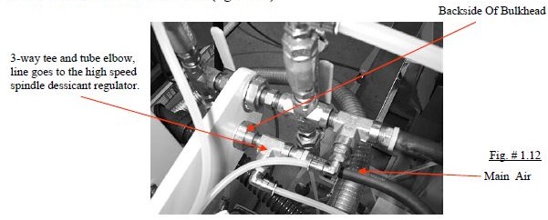
On the backside of the bulkhead, disconnect the main air line and place the 3-way tee and tube elbow in line with the air hose (fig. #1.12).
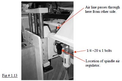
The spindle air regulator and desiccant filter attaches to the machine just behind the spindle slide assembly. To mount, assemble the components as shown in (Fig 1.14) except for the desiccant filter. The white dessicant filter should be mounted last to avoid breaking it. Bring the assembly into place on the machine and attach it with two 1/4-20 x 3/4” hex head bolts and washers ( Fig 1.13).
The air line should pass over the main tube, fastened to the wire tie mount plate placed earlier, form a loop before attaching to the elbow going into the regulator (Fig # 1.13).
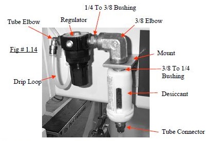
Now attach the desiccant filter to the elbow and attach the air line to the filter (Fig # 1.14).
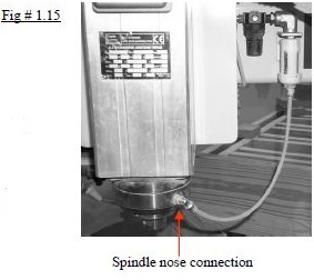
Attach the other end to the nose of the spindle (Fig # 1.15). Allow enough slack in the line to allow full
travel of the spindle slide (Fig. #1.10).
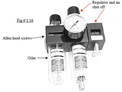
Remove the filter lubricator by removing the hose and
existing hose barb. Next using a 3/32” allen wrench
remove the oilier screws. Detach the oilier and discard the O-ring (Fig. # 1.16). Reattach the hose barb and hose to the regulator.
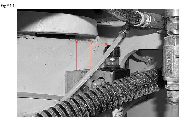
The oilier is attached to the wizard arm with an angle bracket. To correctly position this bracket measure
in two inches from the right corner of the end plate and two inches down from the top plate. Mark
and drill two 1/4″ holes and tap with 1/4-20 threads and attach the bracket (fig # 1.17.)
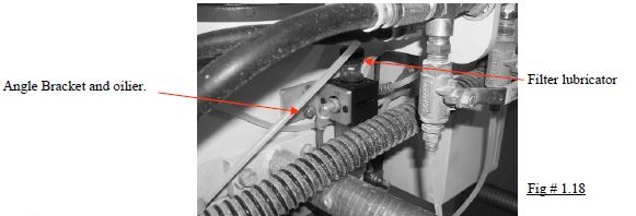
Attach the oilier using the existing allen head screws (fig #1.18 ). Connect a string of 1/4”plastic line
from the front air supply fitting to the left side fitting on the lubricator.( This is opposite of what the
arrow flow mark shows, but the lubricator works better this way) Next, attach another 1/4” plastic
hose line from the right side of the lubricator to the fitting on the back side of the panel that supplies
the air to the top of main spindle cylinder. The lubricator should be set to drip once every 10X the
main spindle goes up and down. Turning the black cap on top is how to make this adjustment.
WATER SYSTEM
A 4-way tee needs to be placed in the water supply line. If you have the “Water Shot”
option the tee should be placed after the water shot tee. This is located on the backside of
the bulkhead (Fig 1.19.)
Align the 4-way tee as shown in (fig 1.19).
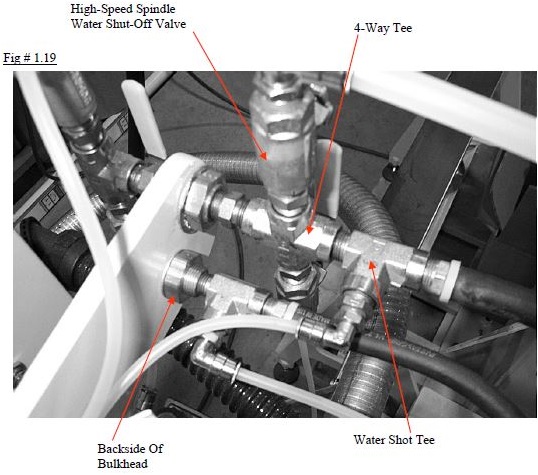
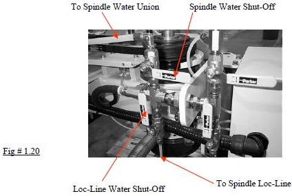
Attach a valve on the top and bottom of the tee and orientate them so the handles face forward when
in the off position ( Fig # 1.20). The valve on top controls the water going to the spindle water union.
The valve on the bottom will control the water going to the spindle Loc-Line.
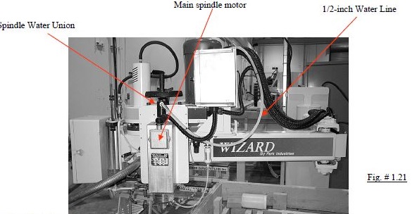
Connect the spindle water union to the valve with an elbow and 1/2-inch poly tubing. Loop the tubing
around the main spindle motor and leave enough slack in the line to allow full travel of the spindle
slide (fig. #1.21) . Wire tie it to the rest of the cords, and attach it to the top ball valve.
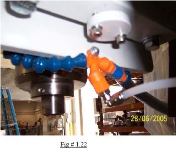
The Loc-Line assembly attaches rear bottom of the spindle rise and fall plate; (Fig # 1.22). Attach with a #8-32 x 3/4” slotted screw, lock washer, flat washer, loc line assembly, and two #8 flat washers in between the plate and loc line assembly.
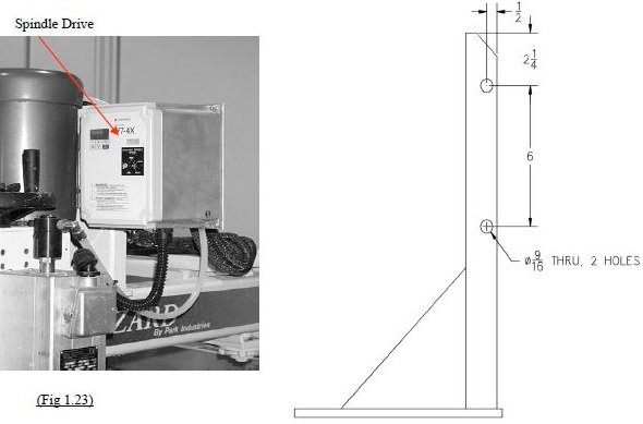
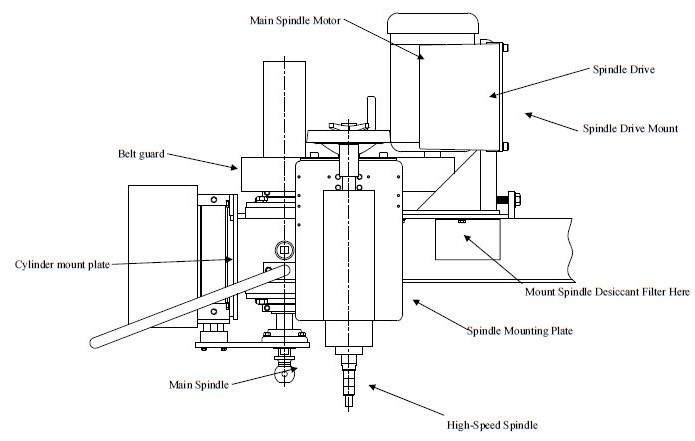
SPINDLE DRIVE MOUNT
The spindle drive will mount to the machine at the main spindle’s motor mount (Fig # 1.23). Drill
two 27/64” holes, on the right hand side of the machine, following the diagram (Fig#1.25).
The spindle drive mounting plate then attaches with two 1 inch long 3/8– 16 NC hex head cap
screws, bevel washer and lock washers.
The spindle drive attaches to the spindle drive mounting plate with four 3/4-inch long #10-32 socket
head cap screws and lock washers.
Two holes need to be drilled in the electrical box enclosure using the 3/16-7/8 step drill (Fig 1.26.
One hole on the back door will be for the spindle select switch. The other hole on the side of the
enclosure will be for the poly tuff to the spindle drive. Observe all precautions prior to drilling into the
electrical enclosure to avoid damaging any components. All metal shavings should be immediately cleaned out of the enclosure.
(Note on older wizard models, the hole in the side of the enclosure may need to be located above
rather than below the existing holes.) Install the 1/2 poly tuff connector into the hole on the side of the box and secure with the plastic nut. Next, Install the 2 position switch in the door.
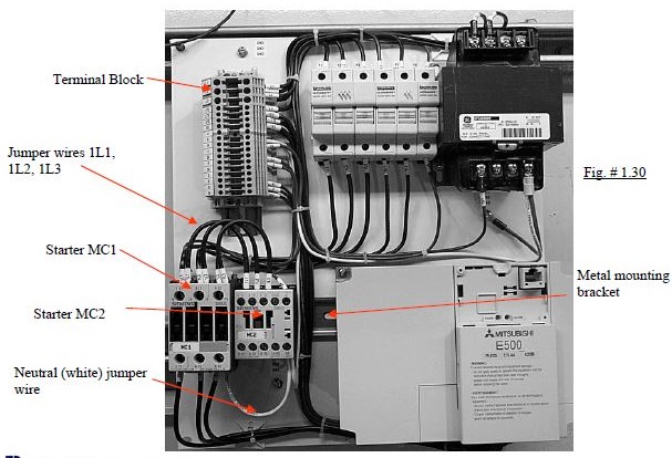
ELECTRICAL ASSEMBLY—cont.
Remove the existing starter MC1 by pulling down and tilting the bottom up, then it should click out (Fig # 1.30).
Remove the existing mounting bracket and install the new 5-1/2-inch long metal mounting bracket. Replace MC1 and add MC2 (Fig # 1.30). (Note: the mounting bracket may need to betrimmed to fit.)
Add the 5 terminal strips from the kit, to the terminal block. After they are added, connect the
wires from the 2 position switch to the left side of the terminals, and tighten (Fig # 1.30). Patch MC2 to MC1 with jumper wires for (1L1, 1L2, 1L3) on the top of the starters. Next, run a jumper wire for the neutral (white) wire from the bottom of MC1, terminal A2, to the bottom of MC2, terminal A2. Run wire (2A) from the right side of the terminal block, to A1 on the top of starter MC2. Run wires from the 2 position switch (1, 2A, 2, 3A, 3)(fig. #1.31), terminate them to the terminal block. Terminate the wires from the spindle drive to 3L1, 3L2, 3L3 on starter MC2. next terminate the ground wire (Green) to a ground on the terminal strip.Reconnect the electrical power and switch on.