
Video’s showing how to dial the Axis 1, A and C axis on a Javelin.
Scan to View on Mobile Device

Required Tools
- Flat Arbor Nut Wrench (Park Industries 60499)
- 14mm Hex Allen Wrench
- Dead Blow Hammer
- Dial Indicator (Park Industries 8200314)
- Magnetic Base (Park Industries 8200315)
- Three small washers
- Set of box end wrenches
- ⅜” socket set
Machine Preparation
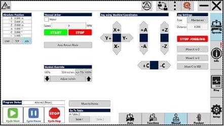
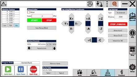
- Navigate to the Operate – Manual screen.
- Axis 1 needs to be at 0° for this ENTIRE machine dialing procedure.
- Turn the Arbor Operation switch to DISABLE.
- Remove the shroud cover and water forks.
- Machine is now ready to continue dialing axis 1, C and A.
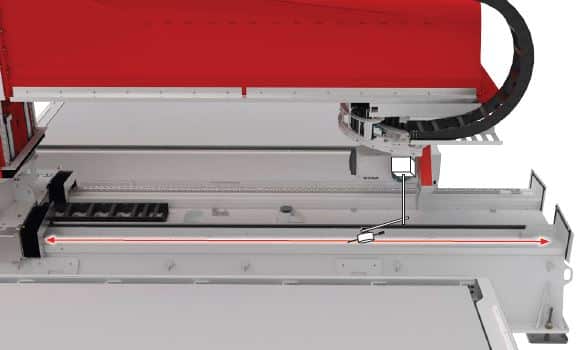
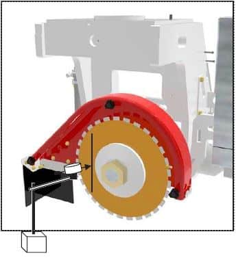
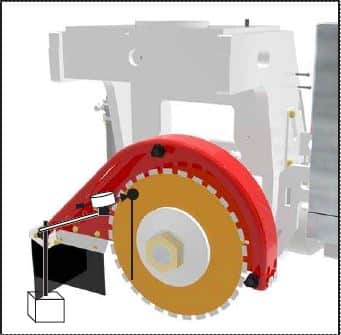
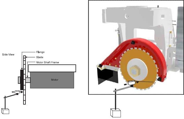
Dialing Axis 1 Determines if the arm is parallel to the X axis.
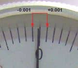
Axis 1 tolerance +/- .001”
Place dial indicator on arbor.
If needed use the pendant to lower (Z-) and align the pointer on the side of the bearing rail as shown.
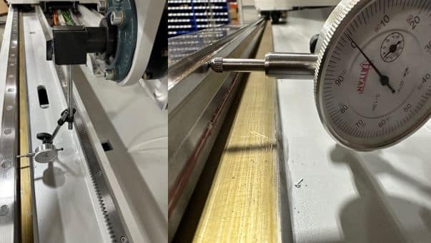
Move the head assembly in Y until the pointer is at one end of the bearing rail.
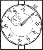
Zero the dial.
Using the pendant move in Y axis running the pointer along the side of the bearing rail to the other end of the bearing rail.
Is the reading +/- .001″?
NO – Axis 1 must be referenced. Go to the next step.
YES – NO adjustment is needed – if continuing the dialing procedure skip ahead to “Dialing the A Axis”
Navigate to the Setup – Move screen and press the Pendant Column Enable button.
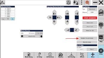
On the pendant select 0 on the rotary dial and select the .001” (F3) button.
Use the pendant to adjust axis 1 as needed. Note you are moving in fractions of degrees so this may take a few tries of checking/adjusting before you are within specification.
Repeat steps 3 – 6 until the reading is +/- .001″ from one end of the bearing rail to the other.
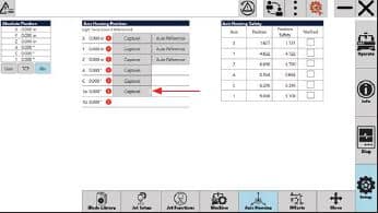
Navigate to the Setup – Axis Homing screen, press the 1a axis Capture button.
Close the HMI, power down for 30 seconds, then power back up and continue setup.
Once you power back up you will need to check the box to verify the axis that you just referenced.
Dialing A axis Ensures the blade is cutting plumb.
Axis 1 MUST be verified and at 0° before continuing.
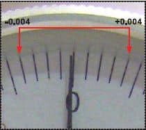
Axis A tolerance +/- 0.004”
Navigate to the Operate – Manual screen
- Press the Move A to 0 button.
- Press the Move C to 0 button.
- Make sure Incremental is displayed under Jog Settings. If Maintained is displayed tap to switch to Incremental.
- Enter 90 into the distance box.
- Press the -C button to position the arbor at -90°.
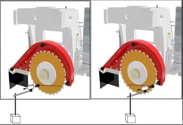
Position the dial indicator so the plunger’s point rests on the left side of the arbor flange.
Using the pendant, move the Z axis until the plunger is pointed at top side of the blade.
With a marker, place a circle were the plunger’s point makes contact with the blade. This is the reference mark.
Set the dial indicator to zero on the big outside dial. Make sure the dial is pushing on the blade enough that the small inside dial is reading a number. Take note of that number.

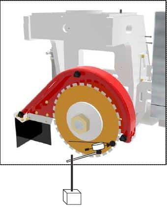
Move the Z axis until the bottom side of the blade is reached.
Rotate the blade so the reference mark is once again were the plunger contacts the blade.
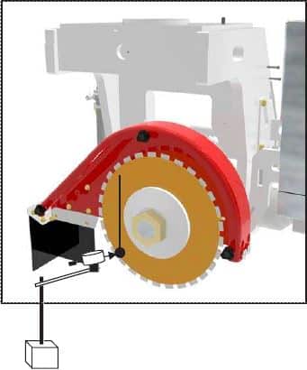
Record the dial indicator reading. Double check that the small inside dial is still reading the same number.
Remove the dial indicator.
Press the Move C to 0 button.
Jog settings should still be set to Incremental and 90 should still be entered into the distance box.
Press the +C button to position the arbor at 90°.
Perform the same dialing procedure you just did when C was at -90.
- Position the dial indicator so the plunger’s point rests on the left side of the arbor flange.
- Using the pendant, move the Z axis until the plunger is pointed at top side of the blade.
- Set the dial indicator to zero.
- Move the Z axis until the bottom side of the blade is reached.
- Rotate the blade so the reference mark is once again were the plunger contacts the blade.
- Record the dial indicator reading.
Split the difference between the two readings.
EXAMPLE: If @ -90 the reading was -.008″ and @ 90 the reading was +.003″ the result will be -.005″.
Divide this number in half (Example result: -.0025″) and this will the target reading while adjusting.
Is the reading zero the same as before you rotated C?
- NO – The A axis needs adjustment, continue with the next step.
- YES – No adjustment is needed you are finished with Machine Dialing the A axis.
Using the pendant rotate the selector switch to the A axis (position 4).
Press the F1 button (.001 setting).
Adjust A axis so that when dialing from top the bottom of the blade the reading matches your calculated amount.
Use the on-screen controls rotate C to -90 and dial the blade from top to bottom as done previously.
Is the reading zero the same as before you rotated C?
- NO – The A axis needs further adjustment, repeat this procedure until the blade dials the same at +90 and -90.
- YES – No further adjustment is needed, continue.
Navigate to the Setup – Axis Homing screen.
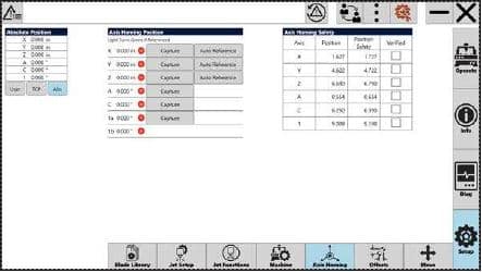
Under the Axis Homing Position in the A row Select the Capture button. Check the box that it is verified.
Close the HMI, power down for 30 seconds, then power back up and proceed.
Once you power back up you will need to check the box to verify the axis that you just referenced.
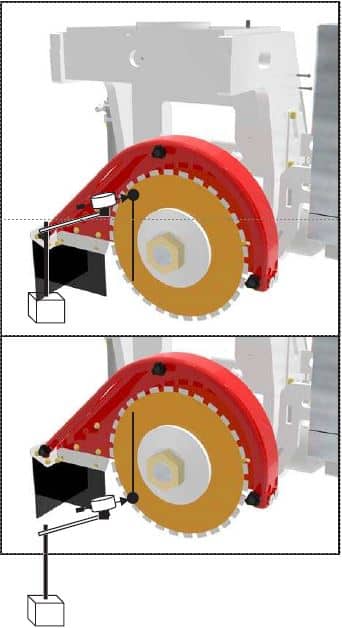
Dialing C Axis Determines if the blade is parallel to the arm at C 90°
Axis 1 MUST be verified and at 0° before continuing.
Axis C tolerance +/- 0.004”
Use Incremental move in the Setup – Move screen to move C axis to -90°.
Position the dial indicator so the plunger’s point rests just below the arbor flange.
Using the pendant move the cross travel assembly on the X Axis until the plunger is on the left side of the blade. With a marker, place a circle were the plunger’s point makes contact with the blade. This is the reference mark.
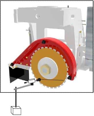
Set the dial indicator to zero on the big outside dial. Make sure the dial is pushing on the blade enough that the small inside dial is reading a number. Take note of that number.

Move the head assembly on the Y axis until the other side of the blade is reached and then rotate the blade so the reference mark is under the plunger’s point.
Is the reading +/- .004″ of an inch.
NO – The C Axis must be adjusted. Go to the next step.
YES – NO adjustment is needed
Navigate to the Operate – Manual screen:
- Make sure Incremental is displayed under Jog Settings. If Maintained is displayed tap to switch to Incremental.
- Enter distance of 0.001.
- Press either -C or +C button on the screen Until the indicator reads half of the distance that this side is off from zero.
Re-check the alignment as follows:
- Using the pendant move back to the left side of the blade.
- Rotate blade to position plunger’s pointer inside the reference point circle.
- Set the dial indicator to zero.
- Using the pendant move to the right side of the blade.
- Rotate blade to position plunger’s pointer inside the reference point circle.
- Read the dial indicator.
Is the reading +/- .004″ of an inch.
NO – Repeat steps 39 and 45 until the tolerance is achieved.
YES – NO additional adjustment is needed, go to the next step
Navigate to the Setup – Axis Homing screen.

Under the Axis Homing Position in the C row Select the Capture button. Check the box that it is verified.
Close the HMI, power down for 30 seconds, then power back up and proceed.
Once you power back up you will need to check the box to verify the axis that you just referenced.