
It is very important that before running your new spindle with the used tool holders you have completed what is highlighted in the spindle care document. See Spindle Care: https://www.parkindustries.com/service/belt-drive-spindle-care/
Scan to Read on Device:

Before beginning the spindle replacement procedure follow these steps!
Position the machine to the front over the table for easier access to the spindle.
Remove the tool from the spindle.
Shut off and lockout air pressure to the machine. Be sure to drain any air left in the system by cycling the drawbar a few times manually.
Turn off and lockout power to the machine.
Turn off water to the machine.
Items needed
You will need the following tools to complete the installation.
3/8” drive ratchet
5/16” Allen head socket for a 3/8” drive ratchet
Extension for 3/8” drive ratchet (equivalent to 12”)
Standard Size open end wrenches for air fittings
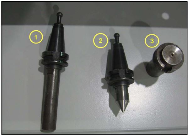
Specialty tools that were included with the machine (see figure below)
- Spindle Height Gauge
- Spindle Pointer Tool
- Tool Rack Receiver Tool
- Magnetic Base (not illustrated below)
- Dial Indicator (not illustrated below)
Disconnecting Air, Water, and Electrical connections

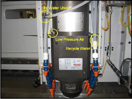
NOTE: To help during reassembly, it is suggested to take a picture of the connectors.Disconnect the cables/hoses from the top of the spindle. Unscrew the water union from the top of the spindle. The water union is a Left Hand Thread.
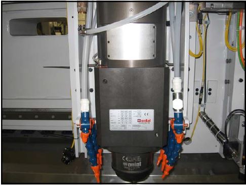
Disconnect the hoses for the water union, low pressure air, and recycle water to gain clearance to the spindle bolts. There are 2 coolant lines toward the back of the spindle that you may remove at this time, but if you can not get to them then wait until the spindle is unbolted.
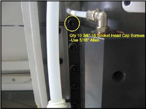
It is now time to unbolt the spindle. Using the 5/16” Allen on the ratchet with extension remove 3 bolts from each side of the spindle. Break the other 2 on each side loose but do not remove them. Using a strap that is rated for at least 500 lbs get the spindle so that the weight is off of the bolts. Now you may remove the final bolts and the spindle.
Installation of New Spindle
Before bolting the new spindle on be sure to install all air fittings.
DO NOT INSTALL THE WATER UNION AT THIS TIME
After all fittings have been installed you may bolt the spindle to the machine. The standard practice is to get the 2 top and 2 bottom bolts on each side “snug.” Once those 4 bolts are in place you can unhook from the lifting
device. Then insert and tighten all of the bolts.
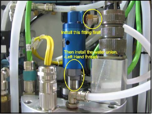
Install the fitting into the water union. Then install the water union onto the spindle. After the water union is installed you may reconnect all of the air, water, and power connections.
INSTALLING THE UNION ON THE SPINDLE FIRST WILL DAMAGE THE WATER UNION AND WILL NOT BE WARRANTIED
Spindle Sweeping (Or Dialing in Spindle)
Sweeping in the Spindle is done by inserting the Spindle Height Gauge tool into the spindle and attaching the magnetic base and dial indicator as in the picture. Zero the dial indicator out in the position A (of below drawing). Then turn the spindle by hand until the point of the dial indicator is in position B. The two sides should be within .003” on 3” from centerline of the spindle.
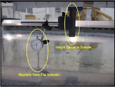

If the spindle is not hanging straight loosen the bolts on the sides of the spindle and push the top of the spindle to one side (not by the water union). Re-measure and repeat if necessary. Tighten all 10 spindle bolts once the spindle is within specification.
Setting Spindle Height to Table
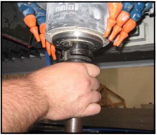
- Insert the height gauge tool into the spindle
- using the following steps:
- 1. On the console set the “Spindle Disable” switch to ON. Press & hold the tool release button
- 2. Insert the tool
- 3. Release button.
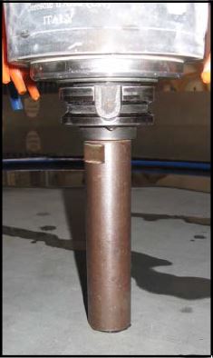
Using the pendant in increments of 0.010” lower the spindle VERY CAREFULLY to the table surface. When the tool is about 1/8” above the surface switch the increments to 0.001” and carefully lower while rotating the spindle by hand. Stop lowering the spindle as soon as resistance is felt when rotating the tool.
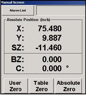
On the Main Menu press the “Manual” button. On the Manual Screen write down the SZ value. Change the sign from negative to positive, and add that to the tool length (number stamped on the side of the tool) to get the Spindle to Work Surface value. In this example the Spindle to Work Surface is 18.363”. 11.460 – SZ value convert to positive number + 6.903 – Length of setup tool 18.363 See the next page for directions on how to access the screen where this value is entered.
On the Main Menu press “Setup” button.
On the Setup Screen press “Machine Setup” button.
On the Machine Setup screen press “Setup Z Dimensions” button.
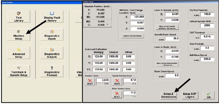
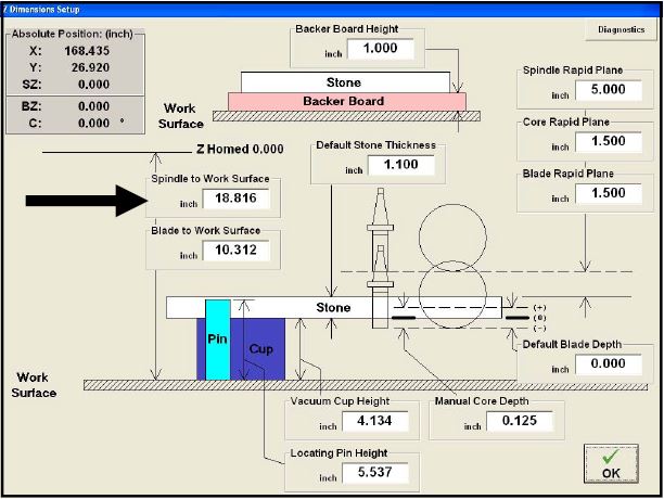
Enter the Spindle to Work Surface value measured in the previous steps.
Setting up the Tool Rack (or Verifying Tool Pocket Locations)
Tool Rack Setup Sequence
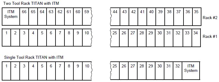
The number of racks/tool holders depends on the model number and build date. Below are the most common configurations. For units without ITM, add two additional holders. The suggested setup sequence is:
Two Rack Systems – Start at position #1 find the X & Y position for all holders in that rack. At last position find the Z position and set spindle orientation. Move to the back rack. Starting on the right side find the X & Y position for all holders in that rack (working right to left). At last position find the Z position only.
Single Rack Systems – Start at position #1 find the X & Y position for all holders in that rack. At last position find the Z position and set spindle orientation.
- 1. Open the Tool Rack Setup #2 screen as follows:
On the Main Menu, press “Setup” button.
On the Setup Screen, press “Tool Rack Spindle
Setup” button.
On the Tool Rack Setup screen, press “Pendant
Assist” button. - 2. On the Pendant Assist screen, press “Access
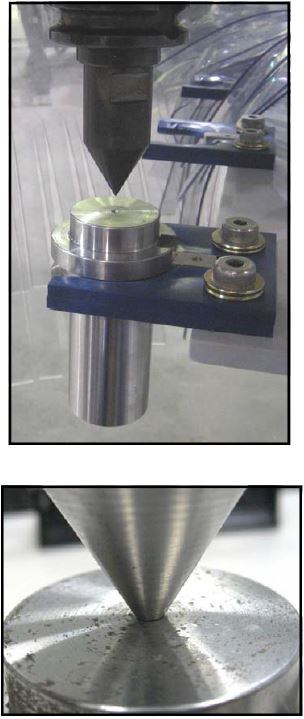
Tool” button. - 3. Load the pointed alignment tool into the spindle.
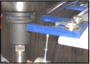
- 4. At the tool rack position to be setup, insert the tool rack jig into the gripper plate. Ensure the jig is fully seated.
- 5. Coarse Movement – Using the pendent (F2 or F3 speed), position the tool over the jig. Stop Z down movement when the tool is about ½ inch above the jig.
6. Fine Movement – Switch to F1 speed on the
pendent. Slowly move the tool on the X, Y and Z axis until the pointed tool is perfectly center in the jig’s hole. - 7. Verify Tool Rack Setup Screen’s position number matches the tool holder position being set up. If not, use the ‘next’ or ‘prev’ pendent buttons to select the correct location.
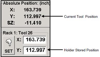
- 8. On the pendant, press wavy line (rapid) button to store the current X & Y position.
- 9. Repeat steps 4 through 8 for all holders in this rack. Front Rack on 1800, only one rack on 1600.
NOTE: After the X and Y position for the last holder in this rack has been stored, DO NOT change the X axis position.
Z Position Setup
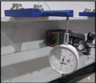
- 10. Using the handheld pendant, move the tool/spindle up ( Z axis) and then away (Y axis) about one foot and then remove the tool rack jig from the holder.
- 11. Attach a dial indicator to the tool rack frame. Position the probe as shown in the photo and zero the indicator.
- 12. Return to Tool Rack Setup screen #1
NOTE: Skip the next two steps if your tool rack setup screen does not have these controls
- 13. Press the orient button.
- 14. If an Orient the spindle dialogue box appears, press ‘Yes’ button.
- 15 Orienting the spindle.
Setting Tool Rack Z Height
- 16. Coarse Movement – Using the pendent (F2 or F3
speed), move the tool on the Y and Z axis until the edge
of the tool holder is about ½ inch from the gripper plate
and the tool holder grooves closely align with the gripper
plate fingers.
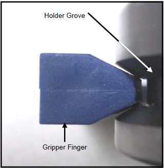
In the next step, the tool holder is moved into the gripper plate. During this movement watch for two key alignments:
1. ensure the tool holder grooves align with the gripper plates fingers (+ or – Z axis)
2. tool holder alignment notch aligns with the gripper plate’s alignment pin (rotational) NOTE: DO NOT move on the X axis during any part of this setup procedure.
- 17. Fine Movement – Switch to F1 speed on the pendent.
Below is a sequence of steps used by equipment installers.
Read all five steps before starting.
A. Slowly move in the plus Y direction.
B. Stop when the dial indicator detects (greater than
0.010) gripper tool deflection.
C. Slowly move on the Z axis until the dial indicator
reads zero again.
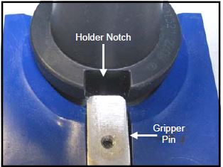
D. Check the alignment of the holder’s notch and gripper’s
pin.
E. Repeat A, B, C and D above until absolute Y position
(one being changed) equals the stored Y axis
position for this holder. These two values are displayed on the Tool Rack Setup screen #1
- In the next step, the tool holder is moved into the gripper plate. During this movement watch for two key alignments:
- 1. ensure the tool holder grooves align with the gripper plates fingers (+ or – Z axis)
- 2. tool holder alignment notch aligns with the gripper plate’s alignment pin (rotational)
NOTE: DO NOT move on the X axis during any part of this setup procedure.

- 18. On the Tool Rack Setup screen, press the“Set” button for the rack being checked.
Tool Rack Setup (Cont’d)
NOTE: The Z position has been entered on all tool holder positions in this rack.
NOTE: DO NOT change the current X, Y, or Z position of the tool.
NOTE: The Z position has been entered on all tool holder positions in this rack.
NOTE: DO NOT change the current X, Y, or Z position of the tool.
Setting Spindle Orientation
The next task, set spindle orientation, is done only once per tool setup.
If the TITAN has two racks it is NOT NECESSARY to do spindle orientation
after the Z position has been set for the back rack. The spindle orientation
setup steps are found on the next page.
On units with two racks, once X, Y and Z positions on the second rack
has been setup, exit the Tool Rack Setup screen.
- Spindle Orientation
- This part of the procedure captures a location which the spindle rotates to ensure a tool holder’s notch always aligns with gripper plate’s pin during a tool change operation.
- NOTE: Does your Tool Rack Setup screen have this readout?
- Yes – continue with the following steps
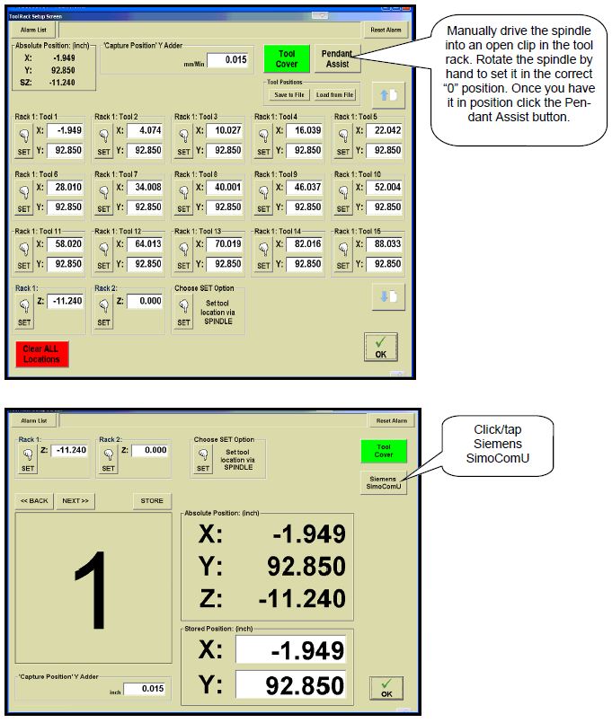
- No – continue 5 slides to ‘spindle positioning’ setting ZERO

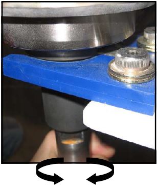
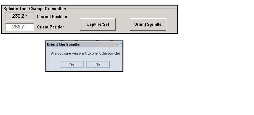
The “Current Position” readout displays the current spindle position. The readout is used to find the tool holder’s center point. As the spindle is rotated by hand, the degree number displayed changes.
- 19. Grasp the tool and rotate clockwise.
- 20. Record the “Current Position” value. _________________
- 21. Grasp the tool and rotate counter clockwise.
- 22. Record the “Current Position” value.__________________
- 23. Add the two positions together and then divide by two (2). ______________________
- 24. Rotate the tool/spindle until the “Current Position”readout equals the number from the last step within 0.2 degrees.
- 25. Press the “Capture/Set” button.
- 26. If the unit has a second tool rack, repeat steps 1 through 18.
If the unit has a single tool rack, the setup procedure is complete. Press “OK” button to return to the Setup screen and then “Main Menu” button.

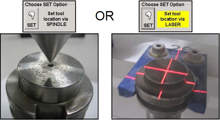
Setting Spindle Offset (Spindle to Laser Offset)
Spindle Offset
The laser light is the operators tool to locate physical positions during digitization, squaring material,
and core holes. On the TITAN the laser light is mounted a fixed distance from the center of the spindle.
This procedure determines the distance between the center of the laser light and the center of
the spindle. This distance (Y & X), when added to the lasers position, determines the correct position
of the spindle.
- Mount the steel pointer provided with the
machine in a 1/2 Gas tool holder and
insert the tool into spindle.
2. Place a piece of wood on the table or a
scrap piece of material on a cup. Place
several layers of masking tape on the
wood surface.
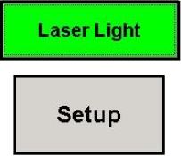
3. On the Main screen, press the Laser
light button, then press the Setup button.
4. On the Setup Screen, press the press
the Machine Setup button.

5. On the Setup Screen, press the press
the Machine Setup button.
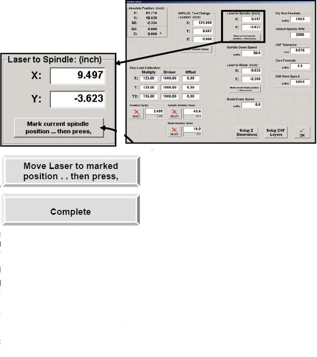
- 6. Locate the ‘Laser to Spindle’ area on the machine Setup Screen
- 7. Using the Using the pendant, slowly drop the pointer
into the layers of tape on the wood block,
leaving only a small indentation. - 8. Press the “Mark current spindle
position . . then press,” button.
NOTE: The wording inside the button just
pressed changed to: “Move laser to marked
position . . then press,”- 9. Raise the pointer so it clears the material.
- 10. Using the Pendant, center the laser crosshairs
exactly over the indentation on the
tape. - 11. Press the “Move laser to marked
position . . then press,” button.
NOTE: The wording inside the button changed
to: “Complete”

12. Return to Main Screen by pressing the ‘OK’ button on the Machine Setup screen and then pressing ‘Main Menu on the setup screen.
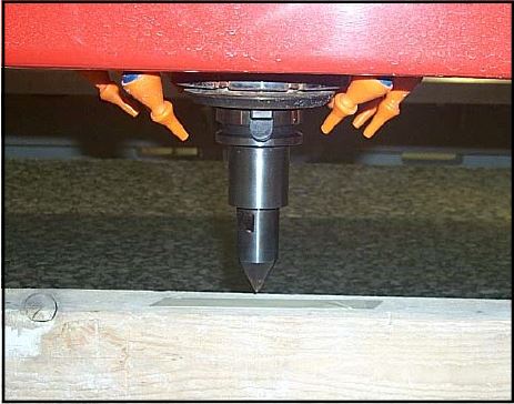
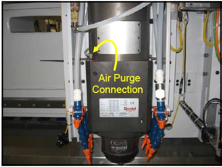
Verify Spindle Air Purge
The spindle is designed with an air purge around the nose cone where the tools are inserted. The purpose of this air purge is to keep water and contaminants from entering the base of the spindle which will eventually damage the lower bearing or motor assembly.
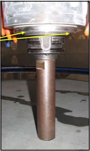
You should feel and hear air coming out of this
area on the spindle. This is the air purge for the
lower bearing (30 PSI).
Failure to provide adequate purge air pressure to the spindle will result in damage or spindle lockup and is not covered under warranty. 30 psi of pressure is required at the nose of the spindle. Due to a loss in pressure through the air line the regulator, located on the side of the machine, must be set at 45 psi.
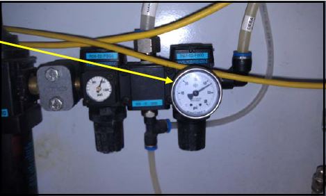
Set the coalescing/desicant air
pressure regulator at 45 PSI.
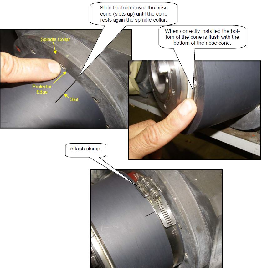
Installation of Spindle Nose Cone Protector
It is very important that before running your new spindle with the used tool holders you have completed what is highlighted in the spindle care document. See Spindle Care: https://www.parkindustries.com/service/belt-drive-spindle-care/