
The Blade/Nozzle TCP Verification procedure is done to improve the blade to waterjet transition. This procedure should be performed after any blade change, after removing or replacing the waterjet cutting head, or if the blade to waterjet transition needs to be improved.
Scan to Read on Device:

before making any changes to robodk, take screen shots of all values.
after making changes in robodk – make sure to delete old pdl code and resend gcode in alphacam.
Create Calibration part in Alphacam
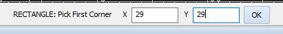
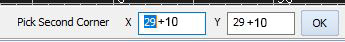
- Draw a 10″ by 10″ square beginning at the 29,29 coordinate and then for second point enter 39,39 or add 10 to previous point.
- Example:
- Offset the geometry shape 1” larger.
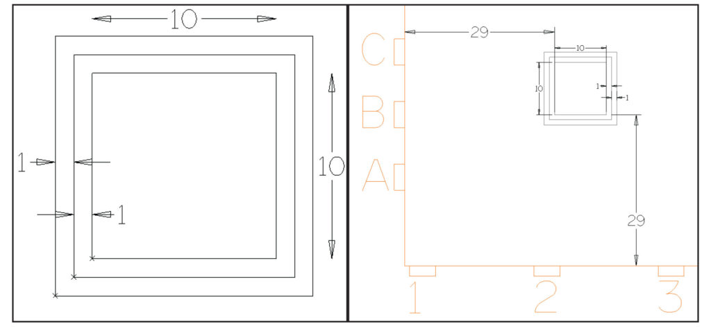
- Offset the newly created offset out another 1″ larger
- Under the Optimus tab, go to Auto Tool Path and select all three squares for tool pathing.
- Once tool pathed, delete the two offset toolpaths as well as the offset geometries.
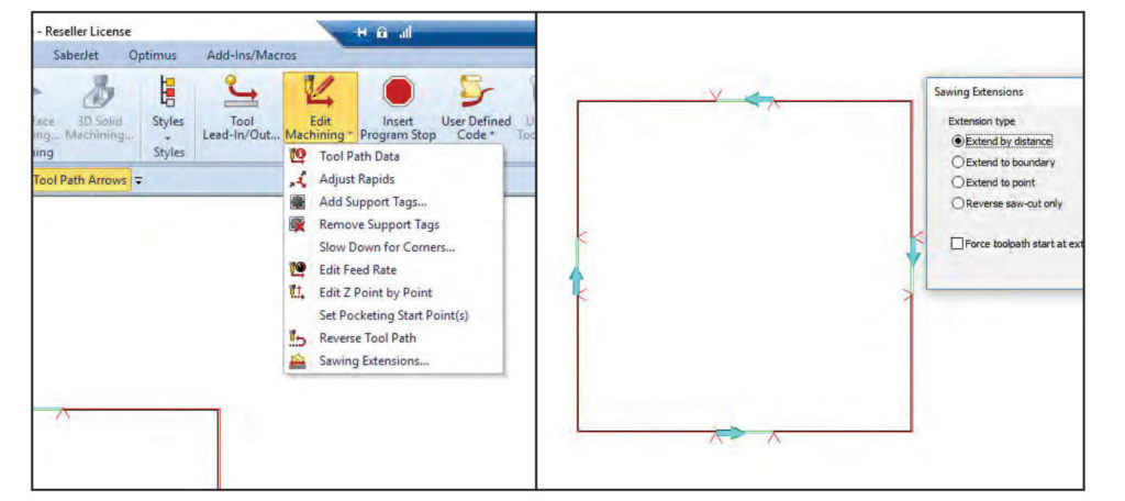
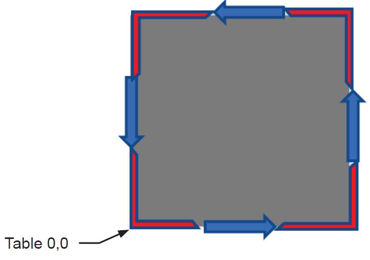
- Under the Optimus tab, select Reverse Cut Direction and reverse the top and bottom blade cuts.
- Go to the Machine tab, and select Edit Machining in the drop down menu select “Sawing Extensions” to verify the tool directions. We want the top and bottom to be counter clockwise. Left and right sides should be clock wise.
- Save the part and send G-Code.
- Under the Optimus Tab select Reverse Cut Direction and reverse all blade directions to be the opposite of the first program. Then go to “Saw Extensions” and verify top and bottom are clockwise, left and right are counter clockwise.
- Save this part with a different name and Send G-Code again.
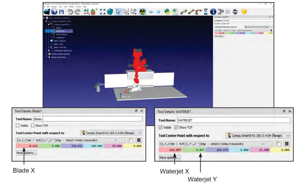
Record current Tool Center Point Offsets in RoboDK
- Open the default robot station in RoboDK
- You will need to get the numbers from Blade1 and Waterjet for each table as well as each setup 2 cm or 3 cm.
- Double click on Blade1 in the menu options. On the right hand side will populate, record the X coordinate offset.
- Double click on Waterjet and record values for X and Y.
Running the machine
- Load the first program under the Operation Auto screen.
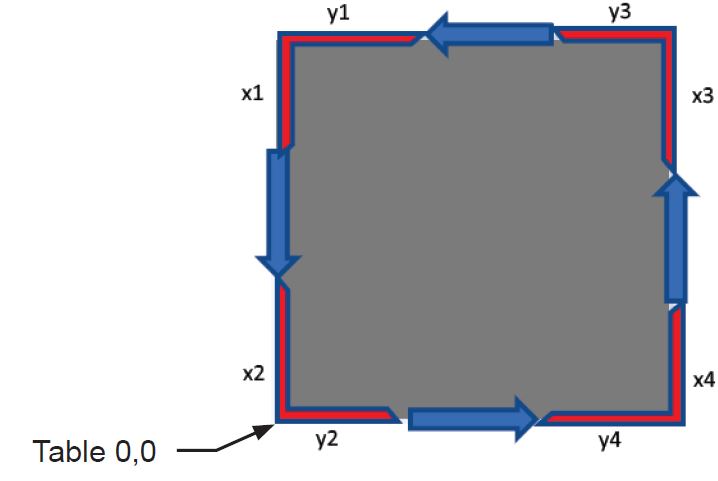
- Run the program, be sure to mark on the piece the origin (0,0) point and which directions the blade cuts were moving. Also label as blade cut1.
- Repeat these steps for the second program and label as blade cut2
Mark the origin point or 0,0 point with a sharpie marker
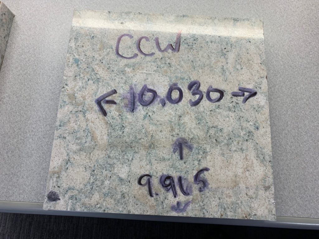
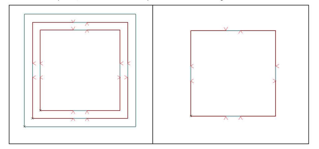
Measure each side of the square. Make sure to measure in the center. If there is a bump out from blade to jet transition measure that as well.
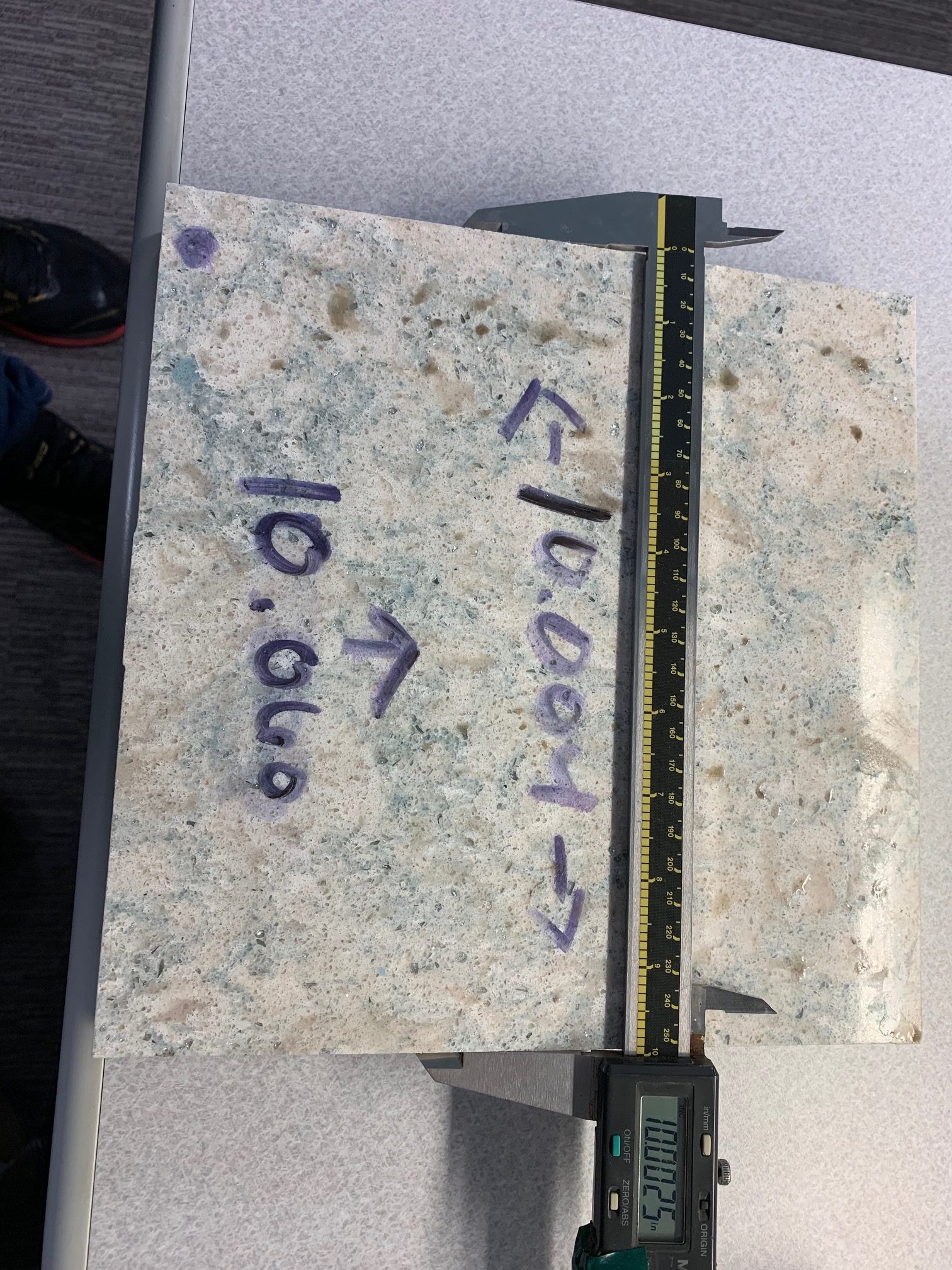
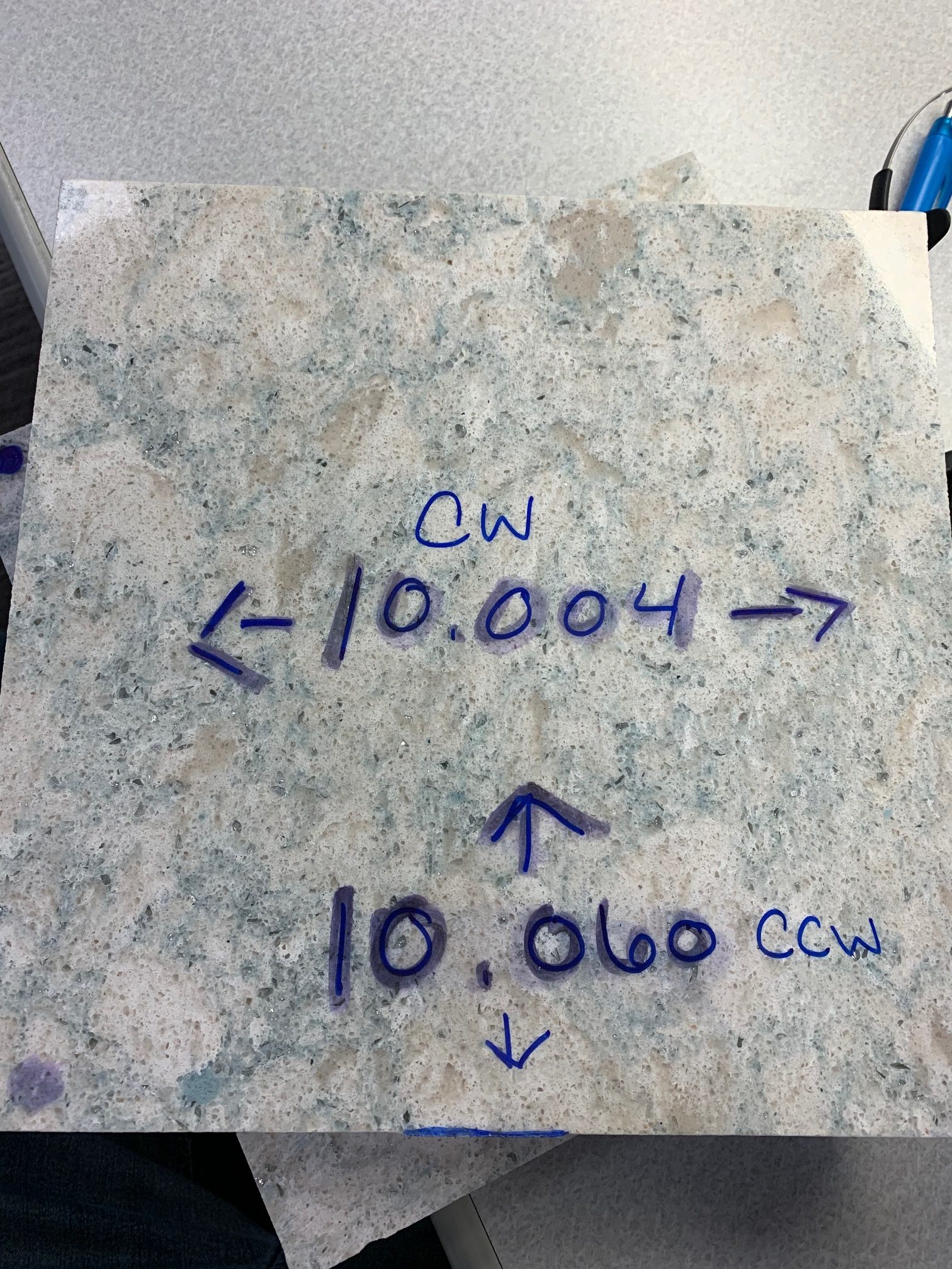
As you measure each cut write dimensions and cut direction X or Y like above.
Notice the blue highlight that shows where the blade cut. Measure off that point, in the center of the square.
Entering the blade Measurements
- Navigate to the Blade Alignment screen. (Setup -> Advanced Setup -> Perform TCP Calibration)
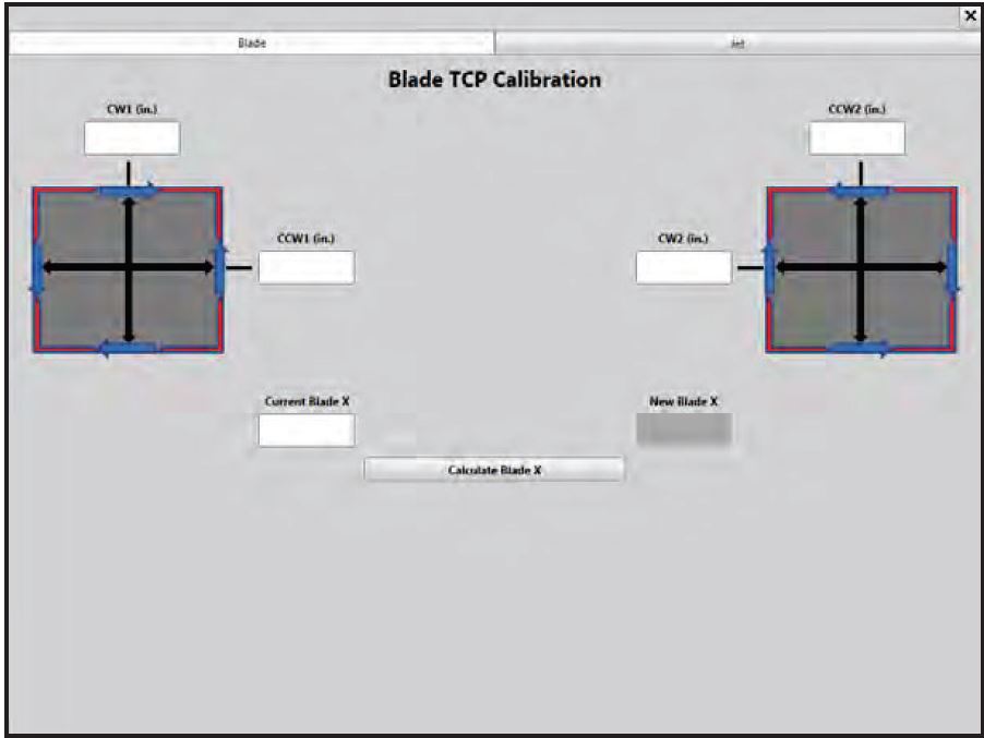
- Enter the value for the blade cut that ran Clock Wise on the first test piece into the CW1 filed.
- Enter the value for the blade cut that ran Counter Clock Wise on the first test piece into CCW1 field.
- Enter the value for the blade cut that ran counter clockwise on the second cut into the CCW2 field.
- Enter the value for the blade cut that ran clock wise on the second cut into the CW2 field.
- Now take your BladeX value we found earlier in RoboDK and enter that into Current Blade X field.
- Click on Calculate and you will get a New Blade X value.
- Open the Default Robot in Robo DK for the table we were cutting on and enter the New Blade X in the Blade1.
Program a third piece still 10″ by 10″ to verify the blade is dimensionally acceptable and to adjust the waterjet
- Program a new 10X10 square, all cuts should run CCW on this piece. This is typically how it would happen with the AutoToolPath command.
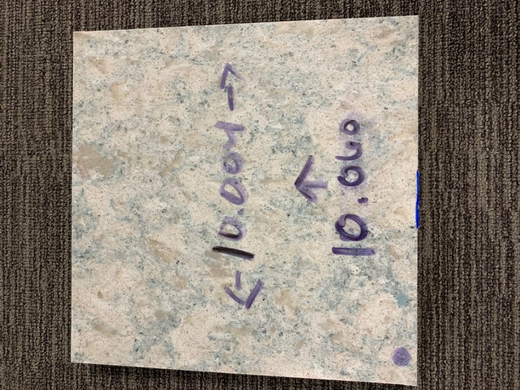
- After running, be sure to mark the orientation of the piece according to the table.
- Measure the square
- If the blade cuts are not acceptable, repeat the previous steps.
- We will use this square to adjust the waterjet.
Measure and record values for Jet X and Jet Y
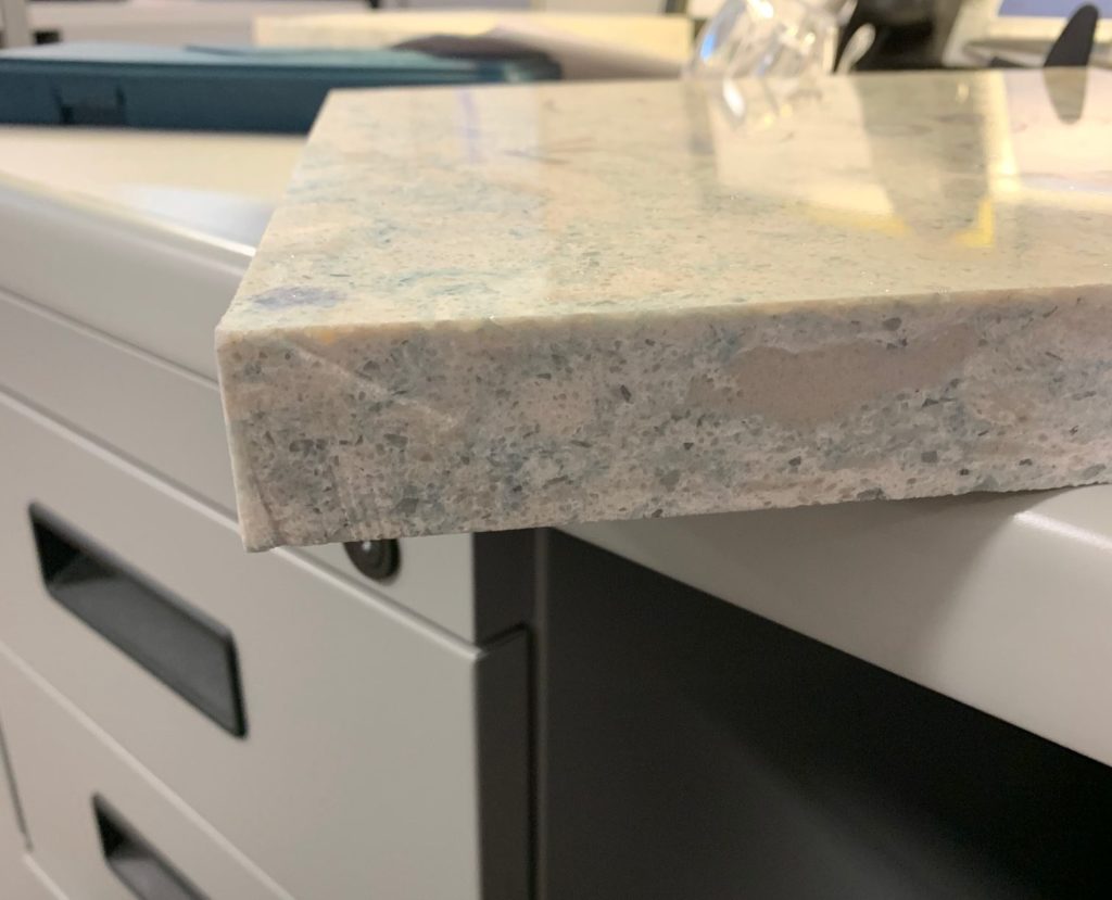
- For each corner on our piece measure the difference between the jet transitions. (The height of the raised portion on the jet)
- If there is no difference or the difference is negative, input 0 or leave field blank.
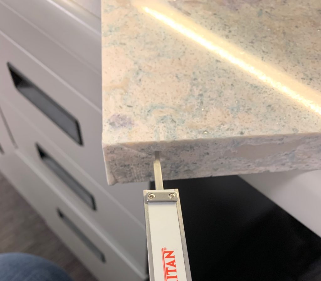
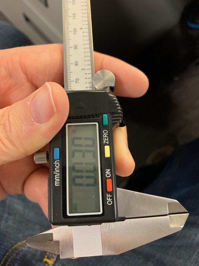
- Input the measurements for each corner into the corresponding fields.
- Enter your current RoboDK Jet X and Y Values and calculate new Jet X and Y Values.
- Enter new Jet X and Y values into RoboDK station for corresponding stations.
- Run one final square to verify measurements and transitions are good.
- If the cut is not acceptable, perform the process again for Blade and Jet to improve calibration.