
Instruction on Perfect Match and how to use the Software Features
At the end of the page there is also a link to watch our videos about using Perfect Match and Slab Maker.
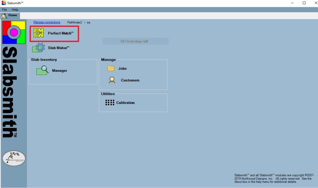
Open Slabsmith by using the Slabsmith Icon on the desktop
Layer Manager Window
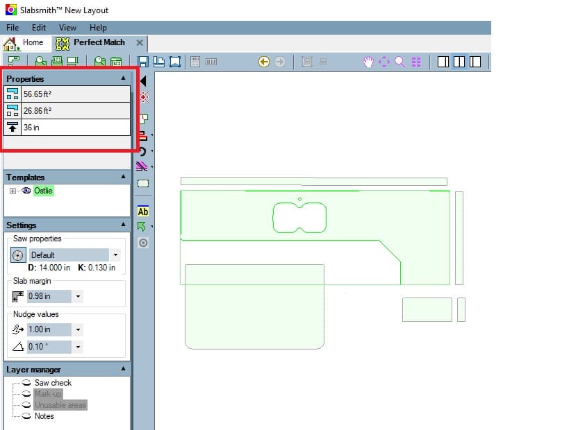
* The first property listed is the total square footage of all of the countertops.
* The second property is the square footage of the current selection. If more then one countertop is selected, the value is the total for all selected countertops.
* The third property is the height/elevation of the countertop.
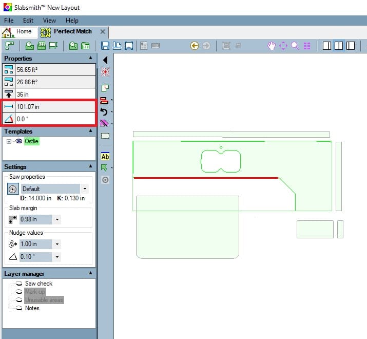
*If a linear edge is selected: The first three properties are the same as the counter in the previous example.
*The forth property of a line is the length of the line.
*The fifth property is the angle of the line.
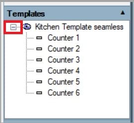
Counter tree:
* Click on the + next to the DXF file you imported to open a list of countertops in the template.
* It contains an item for each of the countertops in the template.
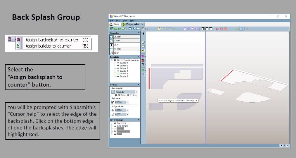
The Backsplash are considered separate counters at this point
Settings Menu
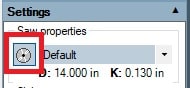
To set up new saw blades or delete old ones, click on the blade icon
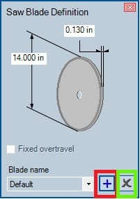
* To add a saw blade and parameters click on the plus sign.
* To delete an existing blade click on the X.
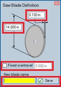
* Fill in the Diameter and Kerf of the Blade
* To use a fixed over travel distance instead of the blade diameter calculation,
click on the box to put a check mark in it and enter an overtravel distance.
* Name the Blade and click Save
* Your Perfect Match blade library should match your Alphacam blade library
* Make sure to select the same blade as you will use when writing the program in Alphacam.
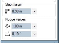
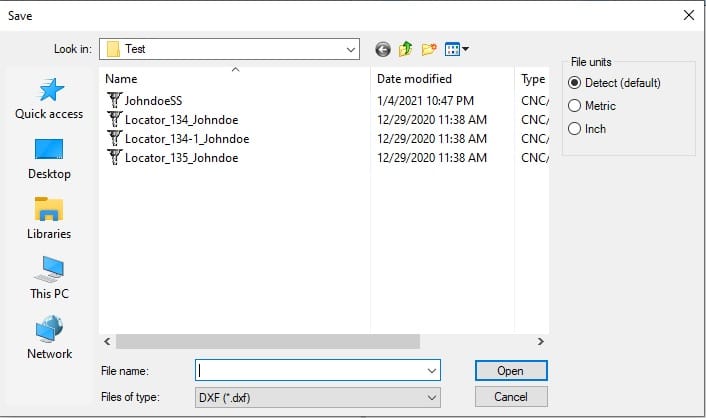
* Slab Margin: Enter the value, in inches, of the border around the slab
that you wish to stay inside of when nesting parts
* Nudge Values: You can nudge the counter tops left, right, up and down using the
arrow keys on your keyboard. The value here determines the distance for each tap.
* You can rotate your counter tops by using ctrl+left /right arrow keys by the degree determined in this box.
* These values can all be changed to your preference simply by clicking in the field and changing the value
Layer Menu
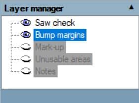
The different layers can be turned on and off by clicking on the oval next to the layer.
When the layer is toggled on it looks like an eyeball.
If the layer is grayed out, that means that that layer was not created when the slab picture was taken.
When toggled on:
• Saw Check shows the blade overtravel. This helps to know if your pieces are too close together
to cut if you are just using a blade the Blade
• Bump margins Places an outline on selected piece showing the nudge value distance when using the
keyboard arrows keys to move the piece Left/Right /Up/Down
• Mark up shows all physical markups if a markup photo was taken when creating the slab
• Unusable areas shows all unusable areas that were digitally marked when creating the slab
• Notes will turn on any notes that have been made when the photo was taken. (not typically used)
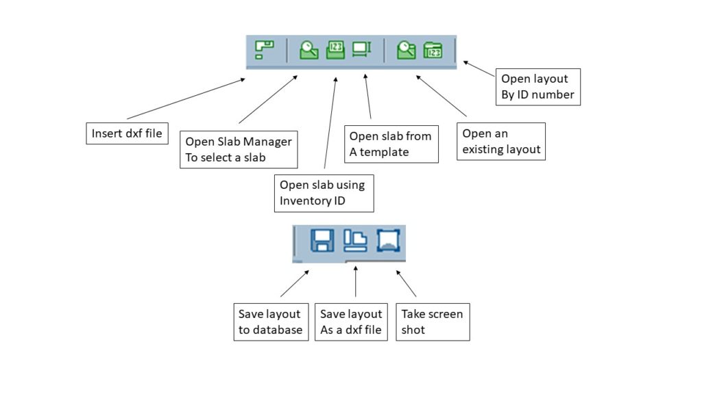
Upper Toolbar Functions
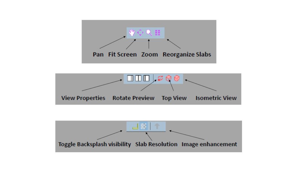
Changing the view using the mouse and keyboard
Zoom – Roll the mouse wheel or the +/- keys on the numeric keypad.
Pan – Both mouse buttons down while dragging or, Spacebar down while left-click dragging.
3D Rotation in the Install view – Push and hold the mouse wheel down while dragging. Move
your mouse forward/backward to tilt the Z axis, move your mouse left/right to rotate about the
current X,Y axis orientation.
Fit all – double left click in the background of the window.
Fit a single counter – double left click on a counter.
Fit an edge/seam – double left click on the edge or seam.
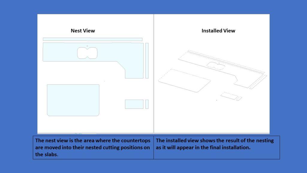
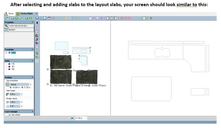
The graphics area contains two sizable windows.
The left window is the “nest view” and the right window is the ‘installed view”.
The graphics area contains two sizable windows.
The left window is the “nest view” and the right window is the ‘installed view”.
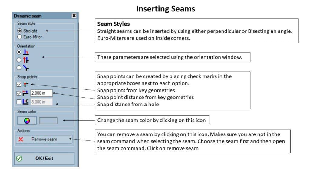
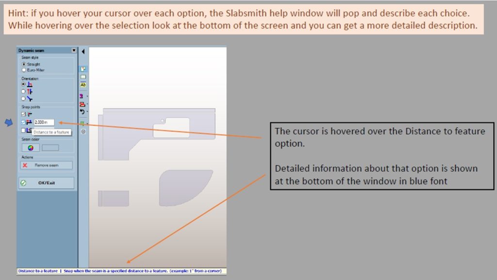
Snap Function
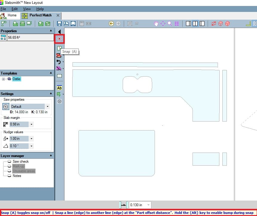
Also note that detailed info about the command is shown at the bottom of the window in blue script
The snap function is used to snap countertops together using the blade kerf of the selected blade.
The snap function is turned on by clicking on the icon or using the shortcut key. It must be turned off when done by doing the same. It is basically toggled on and off.
To use it, select the snap function, click and hold on a countertop edge and drag it to the edge you wish to align it to. It will use key geometries as well as rotate parts as you touch the edge of the countertop that you are dragging it to. You can change the distance between parts snapped by entering a value in the field at the bottom of the screen.
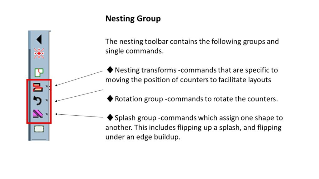
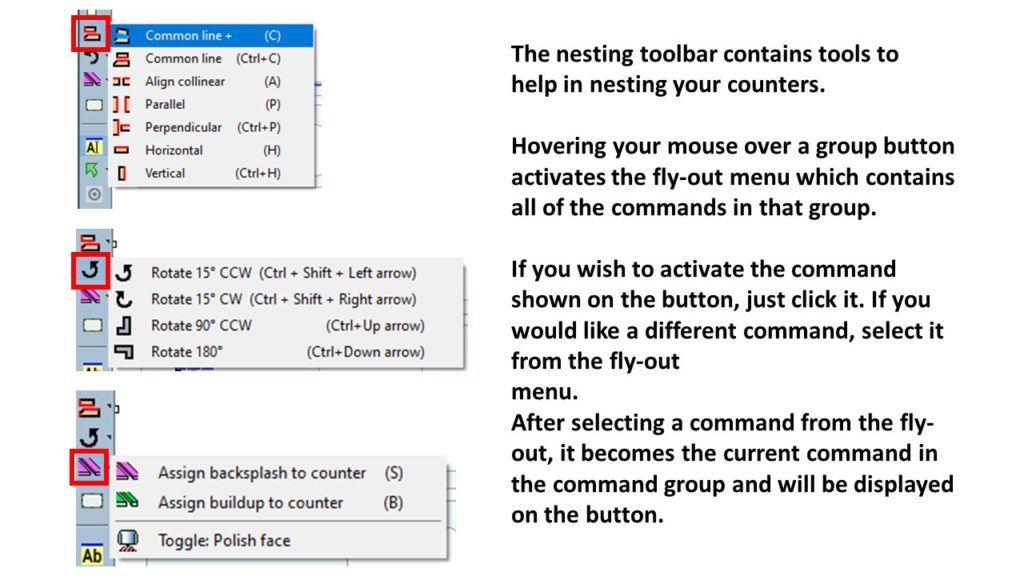
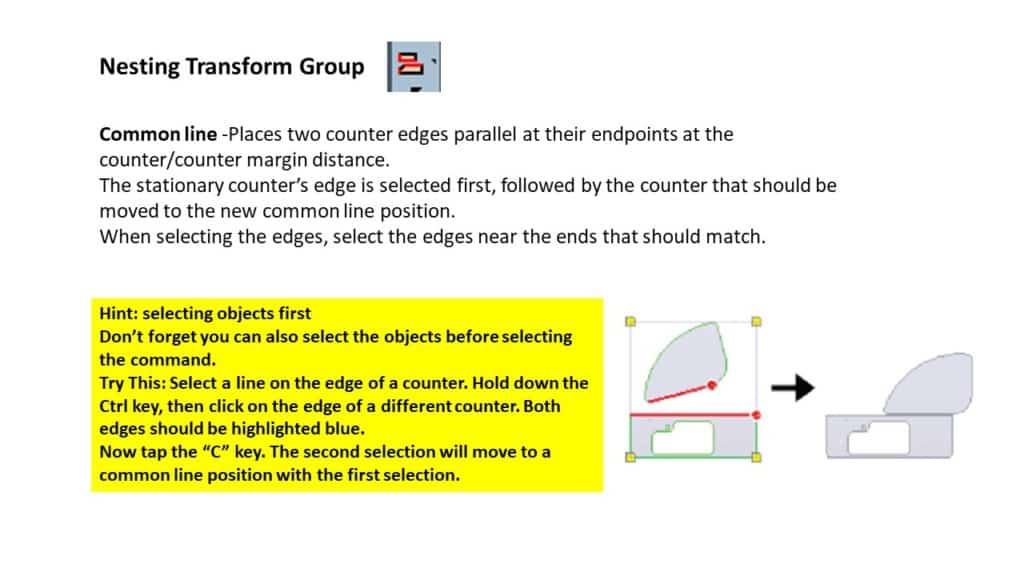
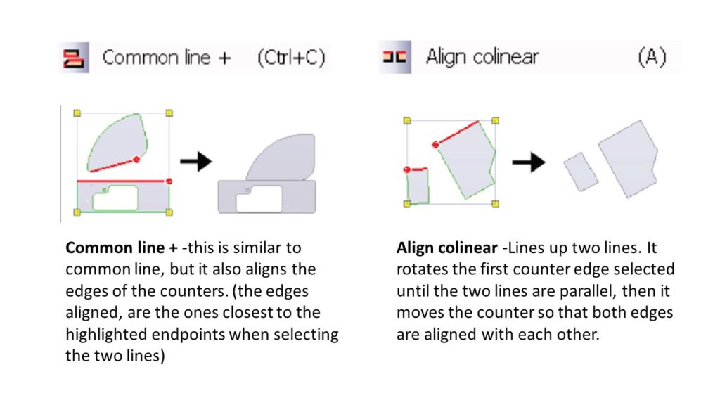
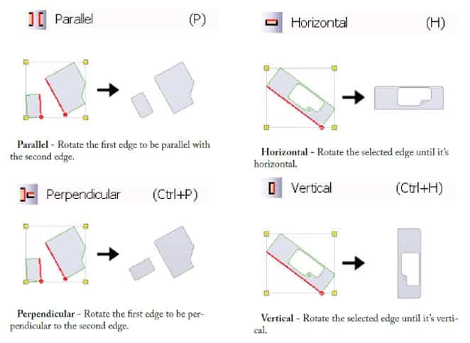
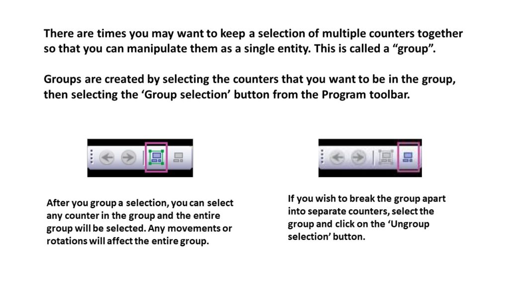
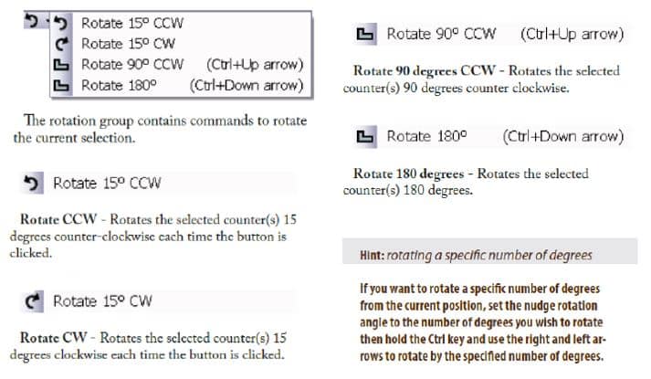
Rotation Group
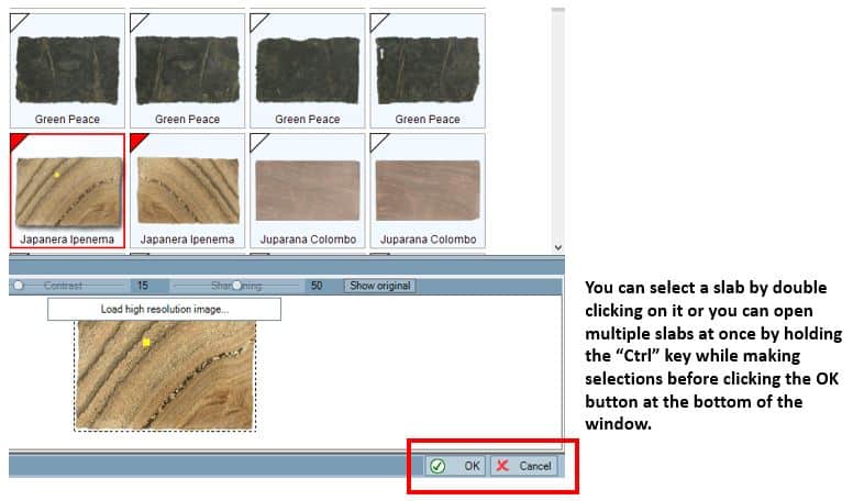
This window should open
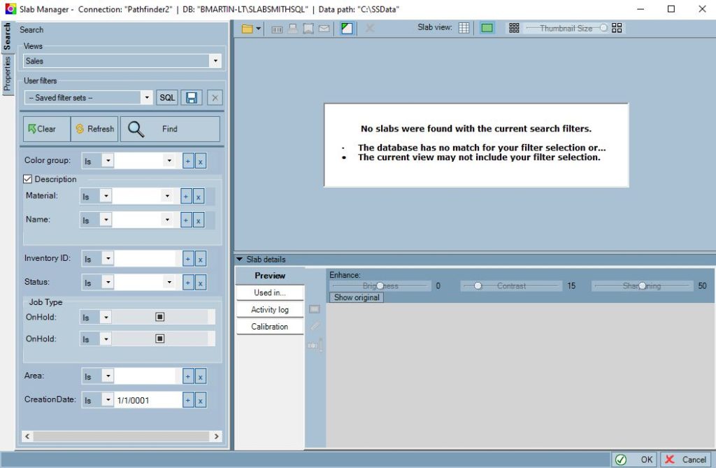
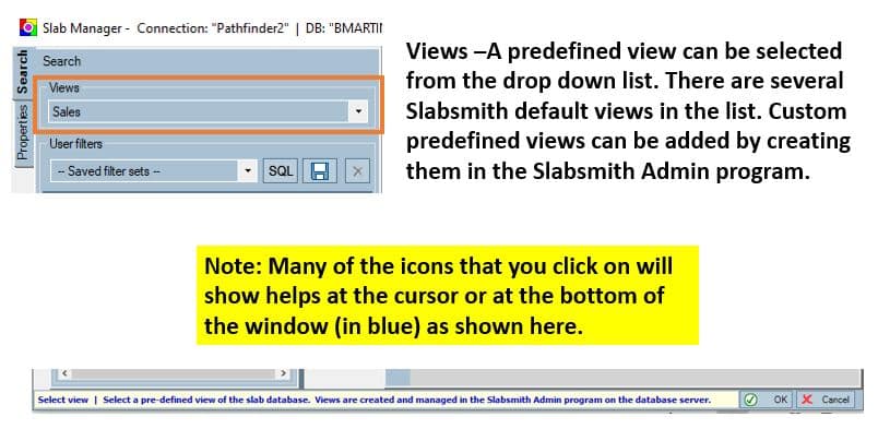
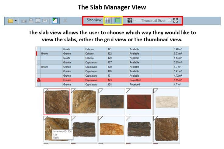
Views
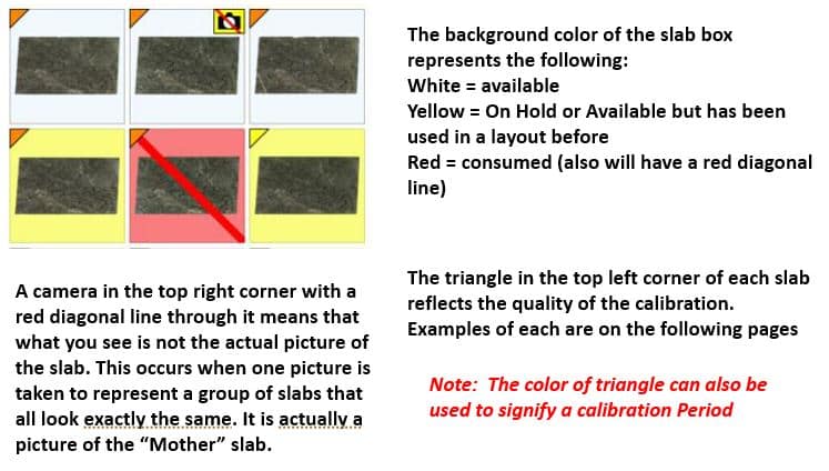
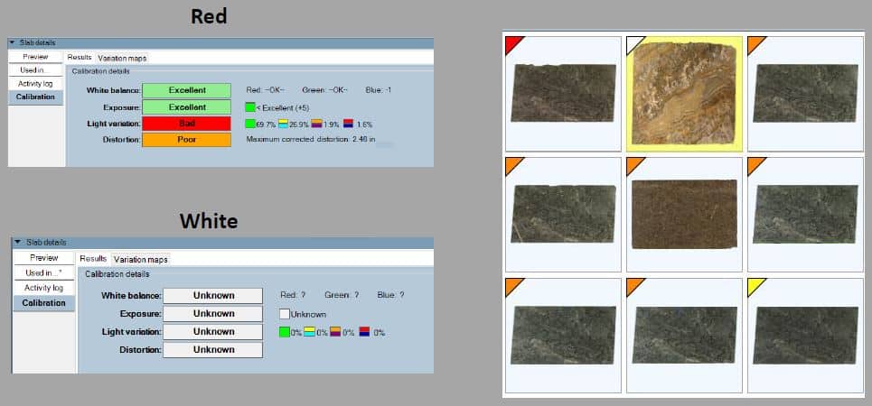
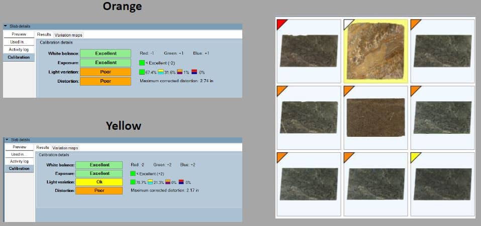
Examples of Calibration Triangle Colors
You may notice that some of your counters that were not red, are red now; this is because they are overlapping the edge of the slabs.
It’s important to note that you can move the material around in the installed view in much the same way you can do it in the nest view.
It’s usually a good idea to start nesting with the largest countertops and most difficult seams.
Take a few minutes and move one of the counters over the slabs while watching the install view. You will see exactly what the installed counter will look
like if the counter is placed on any particular part of
the slab.
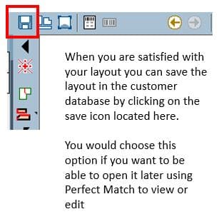
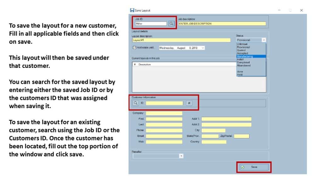
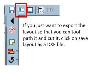
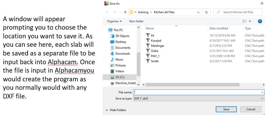
Saving Your Work
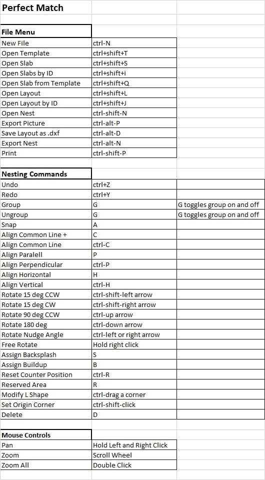
Shortcut Keys
If you would be interested in learning more and seeing some examples in Perfect Match, please watch our video link below “SLABSMITH SOFTWARE VIDEO TUTORIAL SERIES”