
An example of how to program a profiled edge using the Saw on the Saber, SaberJet and Voyager. All settings are examples and may not be the same for all applications.
This guide covers profiling with a Saw Blade. If profiling an arc on the Voyager and Saber you will need FLAT END TOOLS such as the Incremental router or a Gauge Wheel.
Please watch our video link below to create additional tooling.
https://www.parkindustries.com/service/creating-tools-in-alphacam/
Chapters:
0:00 Introduction 0:22 The Geometries and Preparing them 4:23 Selecting the Sawblade 5:34 Setting Cutting information 7:05 Applying the Cut 7:39 Run in Simulation and Send Code
Remember for all profiling….
Take into consideration the thickness, type of material and the depth of the cuts. If needed, draw an
additional roughing shape.
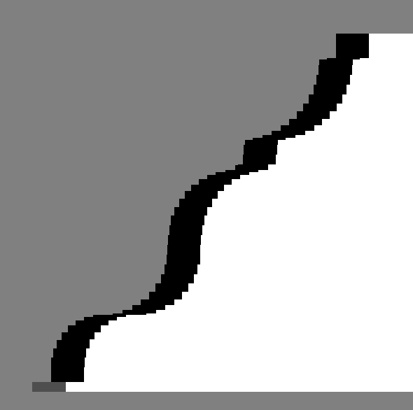
Create Geometry and Side Profile
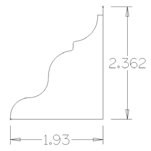
• Draw the side profile of the shape that you are looking to cut to scale. Add dimensions for later
reference.
• Make sure the profile itself is joined, but not joined to the bottom and back edge.
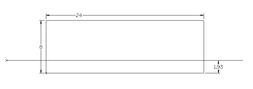
• Draw a top view of the material shape with an offset of where the top of the profile will start.
• Extend the offset out of the material far enough that the full blade will be out of the material as it
leads in and leads out.
should not be joined to the
profile.
Machine-Tool Directions.
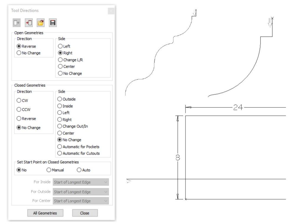
Set tool directions on the side profile and the offset.
• Tool directions on the side profile should start on the top of the profile and will be on the same side
as the tool path.
• On the offset line the tool direction should be set on the side of the line you want your profile to be cut.
In this example our Open Geometries are set to (Reverse, Right). Set Start point on Closed
Geometries is set to (NO)
Saber-Tool Select.
• Under the Saber tab-Tool Select, select or create the blade profile needed for profiling.
• Once selected click on the Saber tab- Select Blade for Profile button next to Tool Select.
Machine-Cut Shape
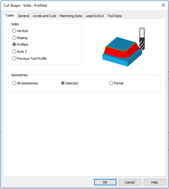
• Types
Under the Sides field select Profiled.
The Geometries field use Selected.
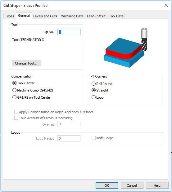
• General
Verify the Tool field has the correct blade selected.
In the Compensation field select Tool Center
In the XY Corners field, choose Straight
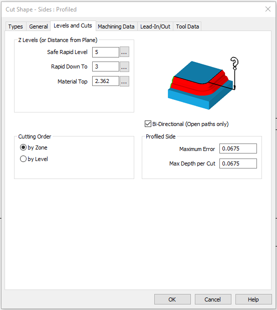
• Levels and Cuts
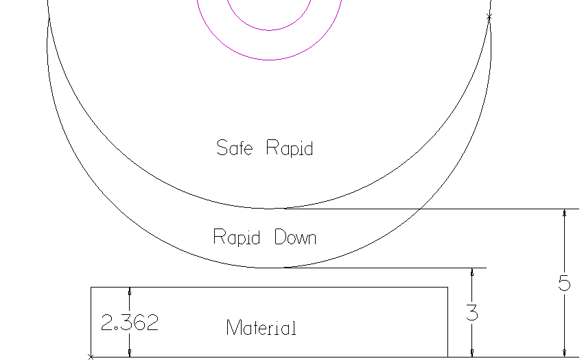
Z Levels (or Distance from Plane) field
Safe rapid level – The Z level that the blade can safely traverse the machining area at a rapid
speed. This distance should be higher than the Material Top. (In this example we use 5 inches)
Rapid Down to – The Z level that the blade can move down to at a rapid speed. Once it reaches this
distance It will start plunging at your programmed down feed.
Material Top – The height of the stone.
Bi-Directional (Open paths only) can be checked if the blade you are using is capable of cutting
forwards and backwards.
Cutting Order – by Zone
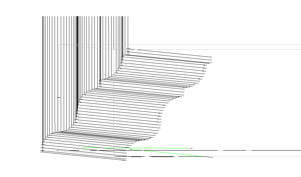
Profiled Side – The larger the number you set, the larger the saw steps will be here on our profile
edge. In this example both are set at .0675.
Maximum error- Step over
Max depth per cut- Drop down
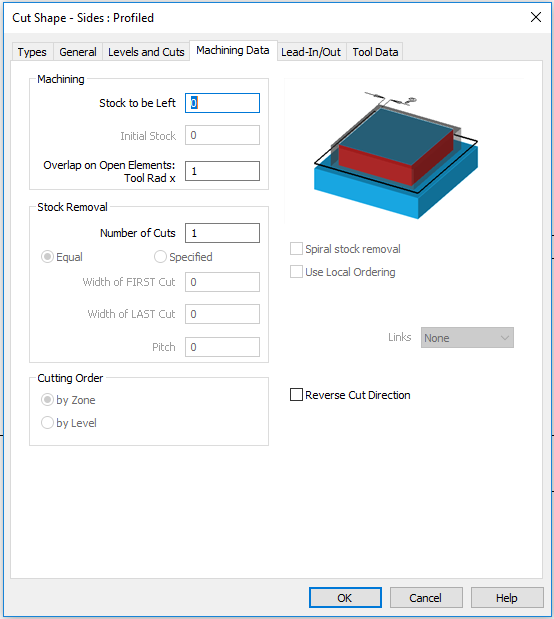
• Machining Data
Nothing needs to be done in this Tab.
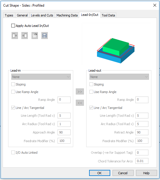
• Lead-In/Out
There is no need for a lead in or lead out here since we extended our offset out of the geometry
enough distance for the blade to clear the stone.
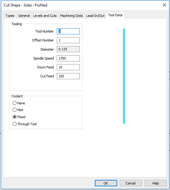
• Tool Data
Verify Blade information here If there is a specific parameter or feed rate that this blade should be
at for this specific job. Changing it here will not affect the original Tool Profile.
• Once all tabs have been gone through click OK.
• On the bottom of the screen it will say “Pick Side Profile”, click on the drawing of the Side Profile.
• “Pick Profile/Geometry Reference Point” Use your Snap keys (F6) then select the top of the profile.

• “CUT SHAPE: Select Geometries” Select Offset line to tool path, then click “Finish”

Depending on material and tool specifications, multiple passes may be needed to reach desired depth
and surface texture.
Simulation (optional)
• Offset material Geometry out .125”.
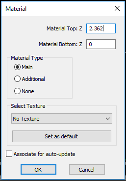
• Under the 3D tab select Set Materials. The bottom of the screen will say “MATERIAL: Pick Geometry
or Solid” Click on the newly created Geometry offset.
• The Material window shown on the right will Pop up. Type in the thickness of the stone.
• Under the View tab select Simulation.
• Click on the Shade Solid Simulation button.
• Click on Play
• Under the View Tab click on the 3D Views for an isometric viewing of
the project or use keyboard shortcut (V).


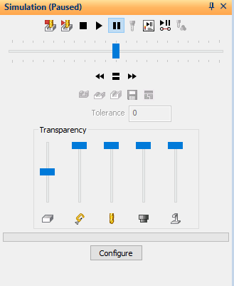
• The blue horizontal bar below the Play button is to adjust the speed
of the simulation.
• After viewing the simulation and the project looks correct,
click the Close Simulation icon.
Note: The saw blade will appear to look like a pencil.

Send G-Code
• Saber-Send G-Code.

Depending on material and tool specifications, multiple passes may be needed to reach desired depth
and surface texture.
If multiple passes are needed return to Step 4. and adjust the Profiled Side under the Levels and cuts
tab for a second pass.
fluting profiles ogee basics learning CAD CAM profiled waves stepover stepdown