
To show an example of how to program a shower pan using the Core bit and Finger bit for the drain hole
and drain flange, and the gauge wheel for the shower pan slope.
A few things to consider before starting.
- The Drain hole cut out MUST be larger than the diameter of the gauge wheel tool, or damage will occur to the tool.
- The stone will be polish side up for this procedure. We recommend planing the back side of the stone before this procedure, to ensure consistent material thickness and good vacuum at the machine.
- Specialty tools are available that may allow you to do smaller drain sizes, and smaller radii at the Profile Geometry corners.
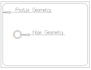
Create Geometry
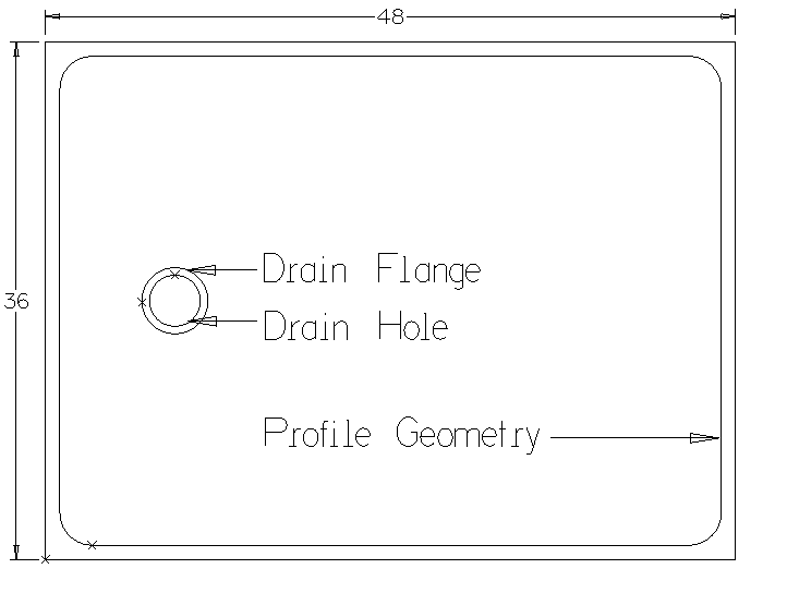
Draw the shape for the application. (Shower pan, Profile Geometry, Drain Hole, Drain Flange)
Set Tool Directions
- Under the Machine tab, select Tool Directions.
- The Profile Geometry, Drain Flange and Drain Hole will all be set to (CCW, Inside, Manual)
Cutting out the drain
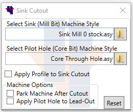
- Under the Titan tab choose Sink Cutouts.
- Choose a Mill Bit style leaving Zero stock to be left.
- Uncheck Apply Profile to Sink Cutout.
- The bottom of the screen will show Select Sink Geometry click on the drain hole, then right click to finish.

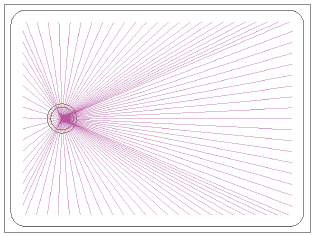
Cutting the Shower Pan Slope
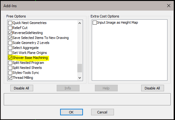
- Under the Add-Ins/Macros tab, click on the Add-Ins button and check the box next to Shower Base Machining, then press OK.

- Under the Machine tab, go to Select Tool and choose the Gauge wheel or the desired tool for the Shower Pan Slope.
- You will see a tool following your pointer on the screen. Left click anywhere on the drawing screen or hit Enter to accept this tool.


- Still within the Machine tab choose Shower Base Machining, and fill out the operation information.
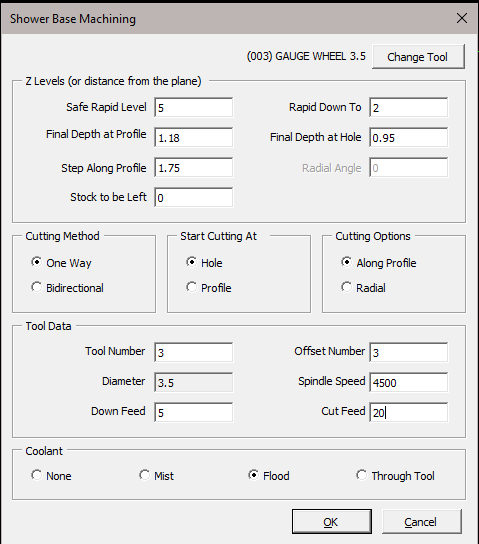
- Safe Rapid Level The Z level that the tool can safely traverse the machining area at a rapid speed. This distance should be higher than the Material Top.
- Final Depth at Profile The height for the shower pan to be, on the outer edges where the slope begins.
- Step Along Profile How far the center of the tool will be from the previous tool path.
- Stock to be Left The amount of material to leave at the profile edge, Usually zero for this application.
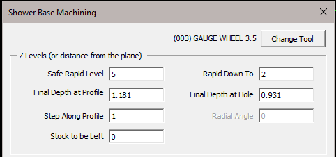
- Rapid Down To The Z level that the tool can move down to at a rapid speed. Once it reaches this distance, it will start plunging at your programmed down feed.
- Final Depth at Hole The depth the stone will be at the drain hole. You may consider not going to the final depth right away, depending on how much the gauge wheel can take off at a time and applying multiple shower base cuts to achieve the needed depth.
Important with a Gauge
Wheel
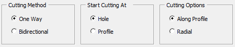
Cutting Method
One Way
Important with a Gauge
Wheel
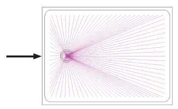
Start Cutting At
Hole
If choosing radial
angle, pick a
radial angle that is
acceptable for your
application.
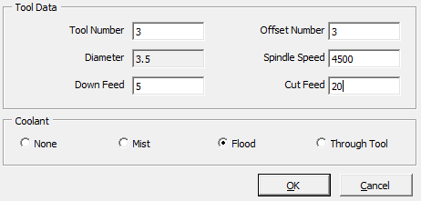
Verify the tool data below.
(Refer to your tool vendor for appropriate feeds and speeds)
- The Bottom of the screen will show Shower BASE: Select Hole Geometry Select the drain Hole Geometry in the drawing.
- Next, the Bottom of the screen will show SHOWER BASE: Select Profile Geometry. Select the profile edge in the drawing that you want the gauge wheel to cut up to.
Repeat this step until the Shower pan is at the desired Final depth at the drain hole.
Cutting out the Drain Flange.
- Create the operation to cut out the drain flange. In this example we will use a Finger Bit.
- Go to the Machine tab, Select Tool.
- Double click on the Finger Bit.
- You will see a tool following your pointer on the screen. Left click anywhere on the drawing screen or hit Enter to accept this tool.
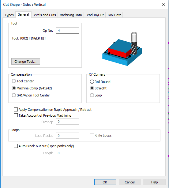
- Then go to the Machine tab, and select Cut Shape.
- Types tab
Under the Sides field select Vertical.
The Geometries field use Selected.

- General tab
Verify the Tool field has the correct tool selected.
In the Compensation field select Machine Comp.
In the XY Corners field, choose Straight.
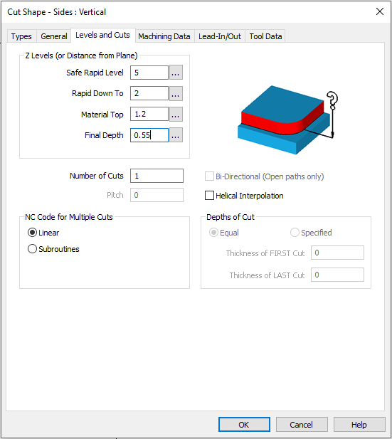
- Levels and Cuts tab
Levels and Cuts– Z Levels (or Distance from Plane) field.
Safe Rapid Level– The Z level that the tool can
safely traverse the machining area at a rapid
speed. This distance should be higher than the
Material Top.
Rapid Down To– The Z level that the tool can
move down to at a rapid speed. Once it reaches
this distance, It will start plunging at your
programmed down feed.
Material Top– The height of the stone.
Final Depth- The thickness of the material after the
cut.
If you have a Default Z value applied to the tool at the
machine, you will have to take that into consideration
when figuring out the Final Depth.
In this example we have a Default Z value of -.125 out
at the machine tool library. We will use .55 for our Final
Depth at the Flange in AlphaCam to achieve a .425 Final
Depth on the part.
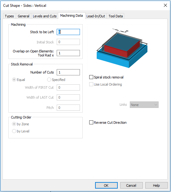
- Machining Data tab
Stock to be Left– The amount of material left after the
cut.
Number of Cuts– Number of passes to take material.
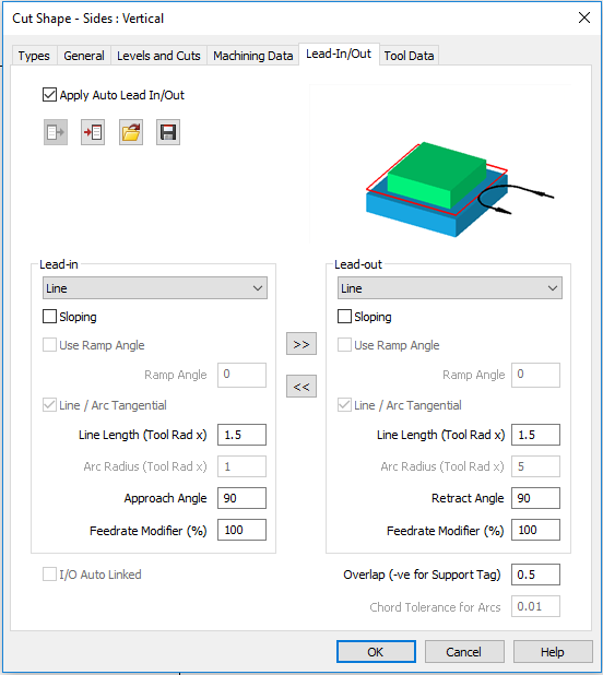
- Lead-In/Out tab
The settings in here will give our tool a starting and
ending point before it gets to the cut path.
- Tool Data tab
Verify Tool information here.
If there is a specific parameter or feed rate that this
tool should be at for this specific job. Changing it here
will not affect the original tool profile.

- Once all fields have been filled in click OK on the bottom of the window, select the Drain Flange and select Finish on the bottom of the screen.


Final pass around Profile geometry.
- Under the Machine tab choose Select Tool.
- Double click on Gauge wheel and left click anywhere on the drawing screen or hit Enter.
- Under the Machine tab choose Cut Shape.
- Fill out the cut information through the different tabs. Adjusting the Final Depth to the desired Profile Geometry depth.
- Once all needed information has been filled, Click OK.
- The bottom of the screen will read. “CUT SHAPE: Select Geometries” Click on the Profile Geometry and Finish.


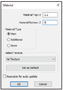
Solid Simulation (optional) to review
- Choose Set Materials under the 3-D tab. Then click on the outside geometry of the shower pan to set the material height.
- To view the simulation, go to the View tab, Show Project Manager Page, and select Simulation.
- It may be best to view the simulation in an isometric view. To do this, under the View tab click on 3D Views button.
- Click the Shade Solid Simulation button to give the drawing a solid appearance.

- Click the Start Simulation button to begin the Simulation.

- Once the simulation is done, click the Close Simulation button.


Send G-Code
- Select the Send G-Code Output button from the Titan tab.

At the machine
When the gauge wheel drops down for the first pass of the shower pan slope, make sure to
turn the feed rate down at the machine close to 5 percent for the first pass. After the first pass
has finished, It will then be OK to be at 100 percent program speed.