To show an example of how to program a Shower pan using the Incremental Router for the drain hole and flange, and the gauge wheel for the Shower pan slope.
Create Geometry
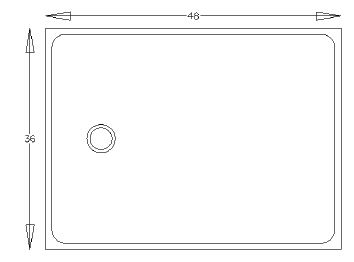
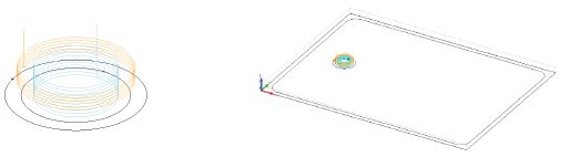
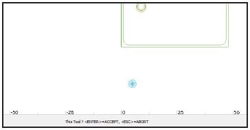
Creating the sink geometry. Draw the shape for the application (shower pan, drain hole & drain flange)
Cutting the Drain Opening
- Cutting out the drain.
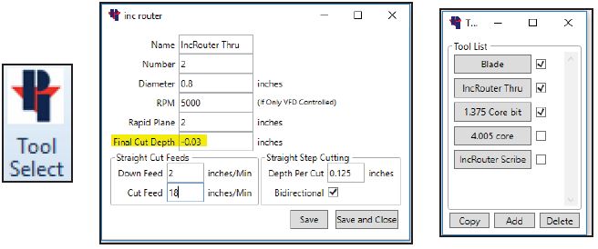
In this example we will use the Incremental router to cut the drain.
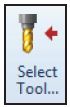
• Set up the Incremental router tool to cut all the way through for the final depth. This will be under the Saber tab, Tool Select.
• Then make sure that the Incremental router profile is activated by having the box checked next to the Incremental router profile.
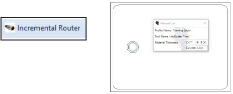
Select the Incremental Router command under the Saber tab. Click on the Drain, then click on
the side to apply incremental routing to (inside), On the bottom of the screen it will say select first point, at this time right click to finish the command.
Cutting the Drain Flange
- Cutting out the Drain Flange
In this example we will use the Incremental router to cut the Drain flange
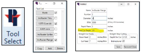
• Set up the Incremental router tool to cut all the way to the final depth at the drain flange. This will be under the Saber tab, Tool Select. Then make sure that the Incremental router profile is activated by having the box checked next to the Incremental router profile.
• Select the Incremental Router command under the Saber tab.
• Click on the Drain Flange, then click on the side to apply incremental routing to (inside).
• On the bottom of the screen it will say “select first point”, at this time right click to finish the command.
Creating the Gauge Wheel for the Shower Slope
- Create the Gauge wheel for the Shower Slope.
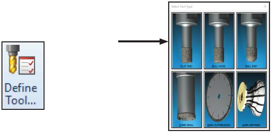
• Go to the Machine tab and select the Define Tool… command.
• Select FLAT END
• Fill out Tool information.
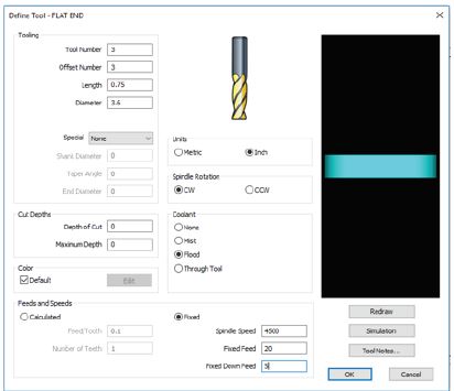
- The Tool Number and Offset number will be the same number as where the tool will be located in the Saber’s machine tool library.
- Measure the cutting portion of the tool for the length and diameter and enter these values.
- Units = inch
- Spindle Rotation = CW
- Coolant = Flood
- Check the box for Fixed
- Spindle Speed = Recommended tool RPM
- Fixed feed = Recommended feed rate in Inches per Minute
- Fixed Down Feed= The Speed the tool will plunge cut into the stone vertically
- The tool gets save the tool into the folder (Windows (C:)>Alphacam>Licomdat>Stool)
Cutting the Shower Pan Slope
- Cutting the Shower Pan Slope
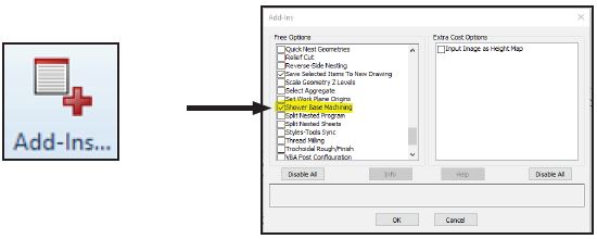
• Under the Add-Ins/Macros tab, click on the Add-Ins button and check the box next to Shower Base Machining. Then go to the Machine tab and Select Tool. - • Double click on the newly created Gauge Wheel.
The newly created tool will show up on your screen and it will attach itself to the mouse pointer until you click the screen.
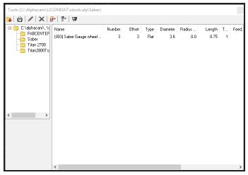
If it is a new tool, it is saved in the Alphacam Tool Library
This is the tools basic cutting profile. Thie cutting feeds and RPMs will be supplied by your Tooling Distributor
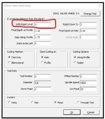
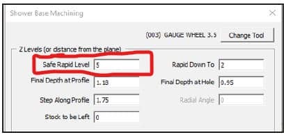
Safe Rapid Level
The Z level that the tool can safely traverse the machining area at a rapid speed. This distance should be higher than Material Top. On the Park Industries 5 axis saws- you may need to have a Safe Rapid Level less than 5 with longer tools so the head of the machine does not try to raise higher than it physically can (which would result in a “Target Position error” out at the machine.
Final Depth at Profile
The height for the shower pan to be, on the outer edges where the slope begins.
Step Along Profile
How far the edge of the tool will be from the previous tool path.
Stock to be Left
The amount of material to leave at the profile edge, Usually zero for this application.
Rapid Down to
The Z level that the tool can move down to at a rapid speed. Once it
reaches this distance, it will start plunging at your programmed down feed.
Final Depth at Hole
The depth the stone will be at the drain hole. You may considernot going to the final depth right away, depending on how much
the gauge wheel can take off at a time and applying multiple shower base cuts to achieve the needed depth.
More movement and cutting data.
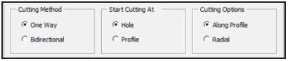
Choose ‘One Way‘ & ‘Hole‘ & ‘Along Profile‘
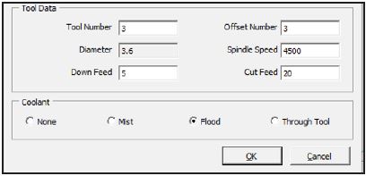
Verify the tool and cutting information is correct and click OK
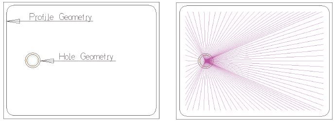
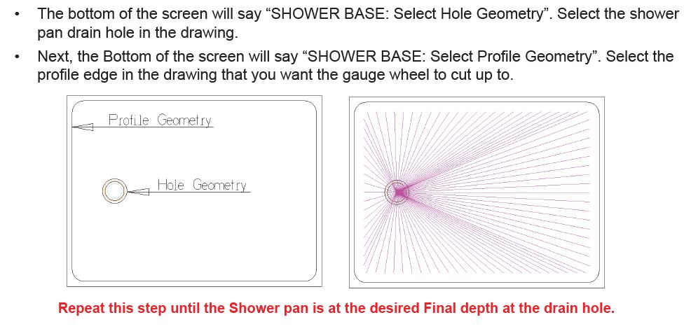
• The bottom of the screen will say “SHOWER BASE: Select Hole Geometry”. Select the shower
pan drain hole in the drawing.
• Next, the Bottom of the screen will say “SHOWER BASE: Select Profile Geometry”. Select the
profile edge in the drawing that you want the gauge wheel to cut up to.
Final Pass around Profile Geometry
Final pass around Profile geometry.
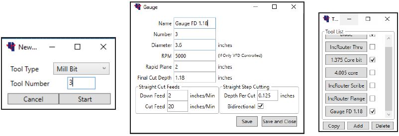
• Create a new tool under the Saber tab, Tool select command.
• Fill in the information fields with the gauge wheel parameters.
• Make sure to set the Final Cut Depth to the profile geometry’s final depth.
• Save and Close
• Then under Tool Select make sure the Gauge wheel is activated.
• Select the Incremental Router command under the Saber tab. This will be used to toolpath the
gauge wheel.
• Verify the correct tool name is being called out.
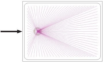
• On the bottom of the screen it will say “ Select Geometry to apply Incremental Routing to.”
Click on the profile geometry.
• Next the bottom of the screen will say to “Pick Side of Geometry”. Click on the inside of the
profile geometry.
• The bottom of the screen will then say “First Point”. At this time Right click with the mouse to
end the command.
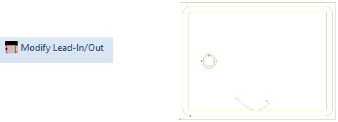
• With the gauge wheel we will need to “Modify Lead-In/Out”, this command is under the Saber
tab.
• Once clicked, the bottom of the screen will say “Select ToolPath To Modify” Click on the Gauge
wheel tool path in the drawing.
• Then it will say “Select Lead In Start Point”, Click Inside of the profile geometry where you want
the tool to start.
• “Select Lead Out End Point” , Click where the gauge wheel should lead out.
Solid Simulation (review is optional)
- Solid Simulation (optional) to review
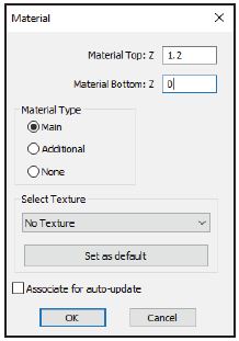
• Choose Set Materials under the 3-D tab. Then click on the outside geometry of the shower pan
to set the material height.
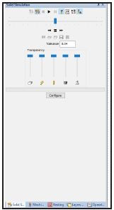
• To view the simulation, go to the View tab, Show Project Manager Page, and select Simulation.
• It may be best to view the simulation in an isometric view. To do this, under the View tab click
on 3D views.
• Click the Shade Solid Simulation button to give the drawing a solid appearance.
• Click the Start Simulation button to begin the Simulation.
• Once the simulation is done, click the Close Simulation button.
- Send G-Code
- At the machine
• When the gauge wheel drops down for the first pass of the shower pan slope, make sure to
turn the feed rate down at the machine close to 5 percent for the first pass. After the first pass
has finished, It will then be OK to be at 100 percent program speed.
Sending the G-Code