To show an example of how to program a Mitered segmented Arc using the saw on the Fusion, Saber, Voyager, and the Saberjet. All settings are examples and may not be the same for all applications.
Create the geometry
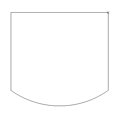
• Draw the shape for the application.
Blade Segmented Arc
- Alphacam only allows straight-line segments to be used with the Undercut or Overcut commands to apply a miter property.
- For this reason, we use the Blade Segmented Arc feature to get the straight lines required on an arc.
- Under the Saber tab select Blade Segmented Arc.

• A pop-up window will appear. Verify the tool name to be used and material thickness.
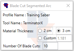
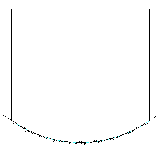
• Enter the amount of blade cuts to be used for the arc. The more blade cuts now, the less clean up later.
• On the bottom of the screen it will prompt us to “Select arc for blade cutting…” In the drawing click
on the arc.

Delete tool paths on the segmented arc
• Go to the Edit tab and select Delete.

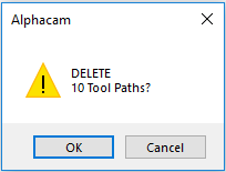
• Window the tool paths created with the Blade Segmented Arc command and click “Finish”.
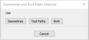
• A window will pop-up to Delete either Geometries, Tool paths, or Both. Select Tool paths and “OK”.
Explode the original geometry and delete the original arc.
• Go to the Edit tab and select Explode. Select the original drawing from step 1 and click “Finish”.

• Go to the Edit tab and select Delete. Select the original Arc and click “Finish”.

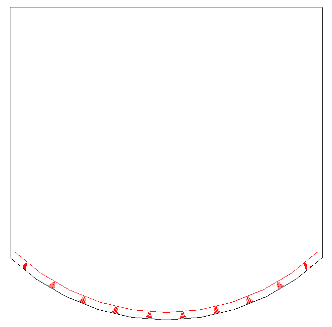
Connect the line segments left from the “Blade Segmented Arc” and do a “Common Line Removal”.
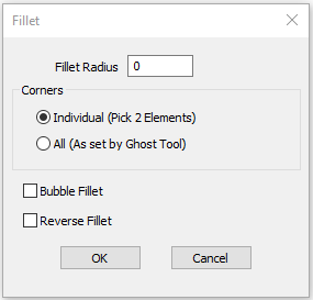
• Go to the edit tab and select fillet. Choose a fillet radius of 0, and select individual. Click “OK”.

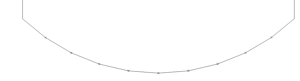
• Select all of the intersections of the segments to fillet, to create the arc.
• Go to the Geometry tab, select Special Functions and choose Common Line Removal.

• Window over the entire geometry shape and click “Finish”.
• Depending on the drawing, other commands such as Trim, Join, and Delete may be needed, to
finish cleaning up the drawing.
• In the end the geometry should have one white X, and should be joined.
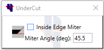
Set the Miter property.
Tool Pathing.
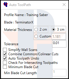
• In Auto Tool Path be sure to uncheck “Simplify Wall Scans”, or keep the tolerance to a low decimal
to avoid the shape of the arc being changed.