This use of this guide requires tools to be made in Alphacam under the Machine Tab. If you are unfamiliar with how to create tools in the Machine Tab- such as FLAT END or USER DEFINED TOOLS- please watch our video link below to create additional tooling first.
Tags: drainboards boards
The following procedure lists the steps necessary to draw and program a drainboard that slopes in multiple directions using the Shower Base Machining add in.
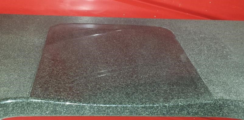
Example of drawing a drainboard
*Changing dimensions and placement of geometry will alter the outcome of your final product. Make adjustments as needed for your desired result.*
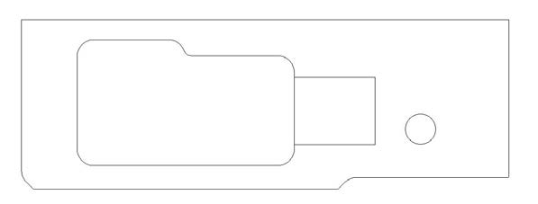
Start with the drawing of your countertop, polished side up.
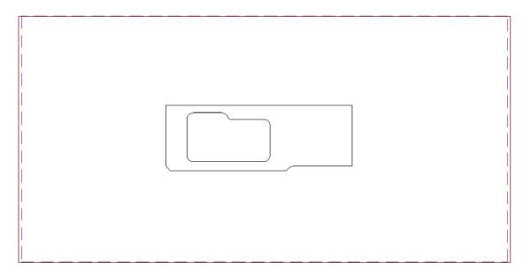
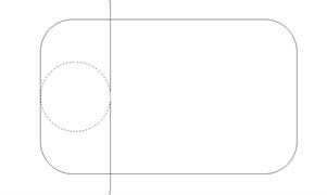
Draw a rectangle to represent your drainboard.

Move Rectangle
Move the rectangle, with a base-point of the midpoint (F7) of the side line to the midpoint (F7) of the sink opening. The rectangle should be outside of your sink on the proper side.
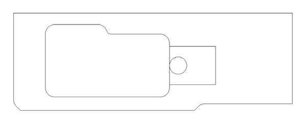
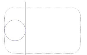
Draw Shower Base “Drain Hole”
Draw a circle that has a larger diameter than your gauge wheel. In this example it has 4.5” diameter, we are using a 4” gauge wheel. This is your Shower Base “drain hole”.
Place Circle on Midpoint of Rectangle
Move the circle, with a base point of the quadrant (F5) and place it on the midpoint of your rectangle on the side that touches the sink.
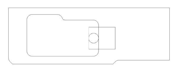
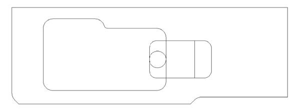
Move Rectangle/Circle Inside of Sink
Move the rectangle and circle inside of your sink. In this example the quadrant of the circle was placed on the midpoint of the sink however you can move it using a distance if desired.
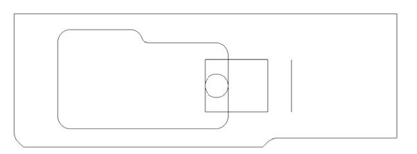
Offset Side of Rectangle on Countertop
Offset the side of your rectangle that is on your countertop, the distance that the rectangle was moved, to retain the original drainboard cutout size.
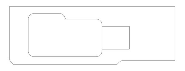
Explode Your Rectangle
Explode your rectangle. Using a radius that is slightly larger than your gauge wheel, Fillet all 4 corners of your rectangle using the offset line to make the rectangle larger. This will also join the rectangle.
Delete the original line of the rectangle
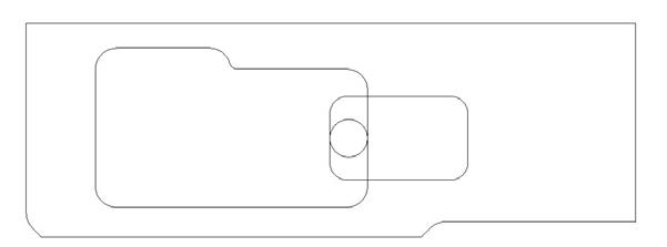
Drawing of the drainboard is complete.
Programming the drainboard
All tool paths should be made with the countertop in its proper place inside the table template so tool paths are not moved.
On the Machine tab, use Select Tool to select your gauge wheel.
Shower Base Button
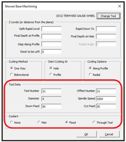
On the Machine tab, click on the Shower Base button to open the following pop-up. Ensure that the proper tool for your machine is selected (arrow below).
If the Shower Base button is not shown, you will need to go to the Add-Ins/Macros tab, Add Ins button to turn on Shower Base Machining.
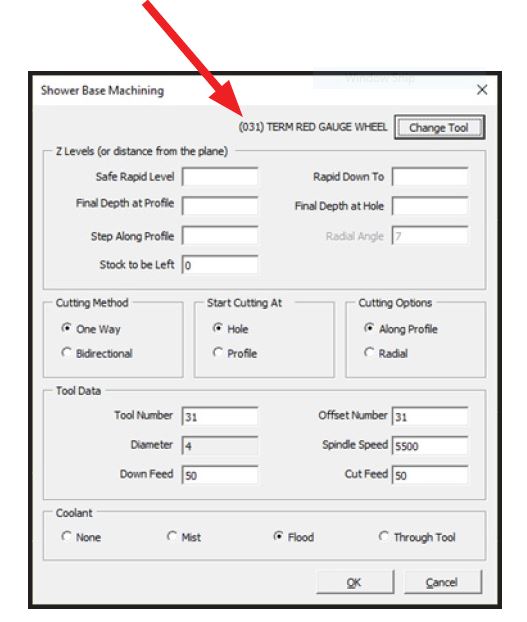
Several fields in this pop-up will need to be completed. They are explained on the following pages.
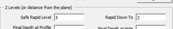
For 3cm (1.25”) material the Safe Rapid Level should be set to 5 and Rapid Down To should be set to 2.
Final Depth at Profile should be set to a number that is just over your actual measured stone thickness so the tool exits the stone at the end of the cut.
Final Depth at Hole should be set to your desired stone thickness at the profiled edge of the sink.
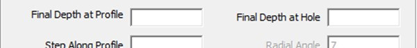
The difference between your Final Depth at Profile and Final Depth at Hole dictate the angle of the slope to be cut.
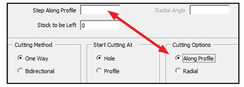
Step Along Profile is used with the Along Profile selection in the Cutting Options. This is the distance between the end of the tool-paths at the profile which is the rectangle in our example above. Smaller numbers will create more tool paths, closer together. Some tool overlap is desired. A good starting point is 2, or half the diameter of the calibration wheel.
Radial Angle is used with the Radial selection in the Cutting Options. This is the angle between tool-paths. Smaller numbers will create more tool paths, closer together. Some tool overlap is desired. A good starting point is 5 degrees.

Cutting Method (shown above) is set the One Way. Start Cutting At (shown above) is set to Hole. Verify that all of the Tool Data is accurate for your tooling. Coolant should be set to Flood. After all settings are correct click on the OK button.
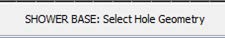
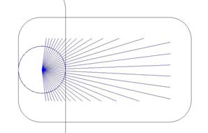
Select the Hole Geometry, the circle in the drawing example created earlier.
Select the Profile Geometry, the rectangle in the drawing example created earlier.

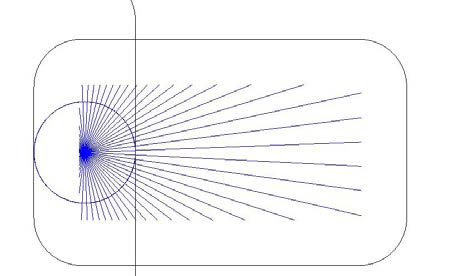
Tool-paths will be created like shown below. Edit the Step Along Profile or Radial Angle to increase or decrease the number of tool-paths.
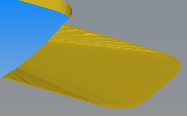
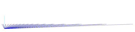
You can verify the tool-paths are sloping by going to the View tab then selecting the Front view. Return to the previous view using the Top button or pressing the V key on the keyboard.
Unnecessary tool-paths can be deleted. They can be found by drawing a circle the same diameter of your gauge wheel and placing them at the end of your tool-path lines. Tool path overlap can also be seen doing this.
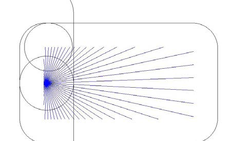
Any circles that are completely inside of your sink indicate that the tool-path can be deleted to avoid “cutting air”. Delete the appropriate tool-paths and all of the circles placed at the end of the tool-paths.
Use Solid Simulation, found in the Project Manager on the View tab, to check the tool path placement.

To reduce the “scalloping” at the edge of the drainboard you can either increase the number of tool paths by changing the Step Along Profile or Radial Angle settings or use Cut Shape to cut the inside of your profile (rectangle in the example above).
When using Cut Shape, on the Levels and Cuts tab set the Final Depth the same as your stone thickness. Numbers in picture below are for example only.
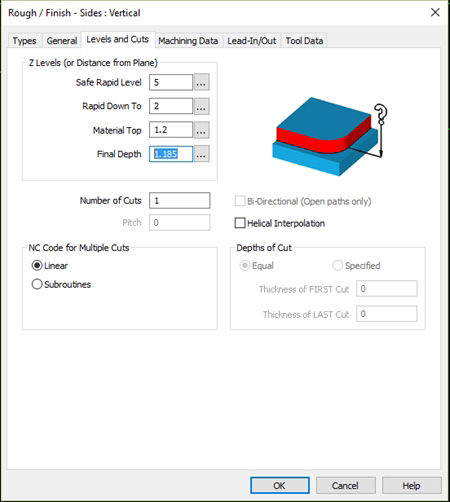
When using the Cut Shape method it is best to only remove very little material at a time allowing for the smoothest transition from the top surface into the drainboard. Solid Simulation after Cut Shape was programmed: