
It is very important that before running your new spindle with the used tool holders you have completed what is highlighted in the spindle care document. See Spindle Care: https://www.parkindustries.com/service/belt-drive-spindle-care/
This procedure illustrates the steps to remove, clean and replace the Quantum Drive spindle. A companion video can be viewed:
Scan to Watch/Read on Device:

Spindle Removal Video:
Spindle Install Video:
Gather tools needed
| Hex head sockets | Wrench/Socket | Special Tools |
| 10mm | 15/16″ Combination | Drawbar Tool (PN 83597) |
| 6mm | 7/16″ Combination | Gripper Set Tool |
| 5mm | 3/4″ Combination | Gripper Puller |
| 1/4″ | 1/2″ Combination | Crowbar |
| 12mm Wrench only |
Disassembly & Removal Steps
- Begin by bringing the spindle to the center and close to the edge of the table.
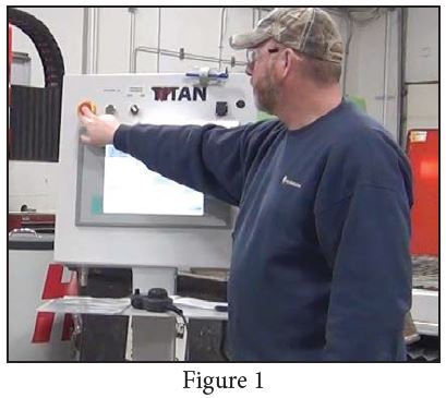
- Push the emergency stop button on the console. [Figure 1].
- Disconnect the safety cable.
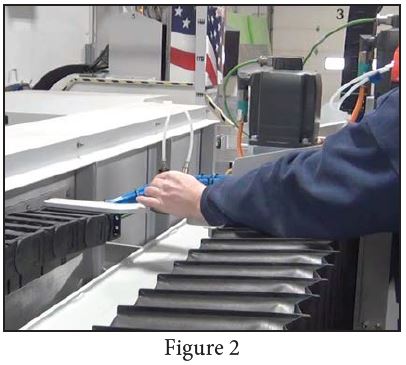
- Slide the shutoff valve for the shroud supply air to turn off air to the shroud.[Figure 2].
- Mark the air-lines to ensure correct reconnection and disconnect air lines from the shroud Disconnect air lines from the shroud.
- Use a ¼” hex socket to loosen the shroud bolts
- Get assistance and lift off the shroud from the machine.
8. Turn system back on and manually remove any tool from the spindle.
9. At the console and go to setup, advanced setup and enter the password SUNRISE.
10. Extend the drawbar.
11. Next, use the gripper tool and the 5mm t-handle hex wrench to loosen the set screw and the
gripper set. [Figure 3]
12. Pull the t-handle hex wrench and Screw the gripper puller in and pull the gripper set out.
13. Retract the drawbar and press the emergency stop button.
14. Shut off main air valve.
15. Remove water lines going to the Water Ring. [Figure 4].
16. Loosen and remove the water ring using a ½” socket.
17. Remove air-lines from the spindle.
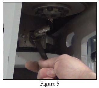
18. Use a 12mm wrench to remove air fitting. [Figure 5].
19. Make sure to clean the spindle housing.

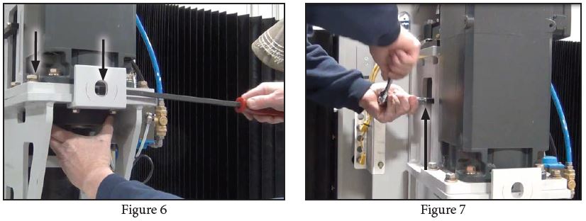
20, Loosen the motor using a ¾” socket. [Figure 6].
21. Use a Crowbar to push the motor back and loosen the belt. [Figure 6].
22. Remove the anti-rotation plate using a 7/16” socket. [Figure 7].
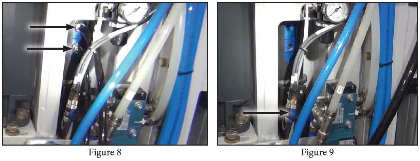
23. Disconnect water lines from the water union [Figure 8]
24. Use a long 10mm hex socket to remove the top fitting.[Figure 8].
25. Then, use a long 5mm hex socket to remove the bottom fitting (the hex end will fit INSIDE of the
fitting). [Figure 8]
26. Disconnect the Spindle Sensor connector. Blue wire. [Figure 9].
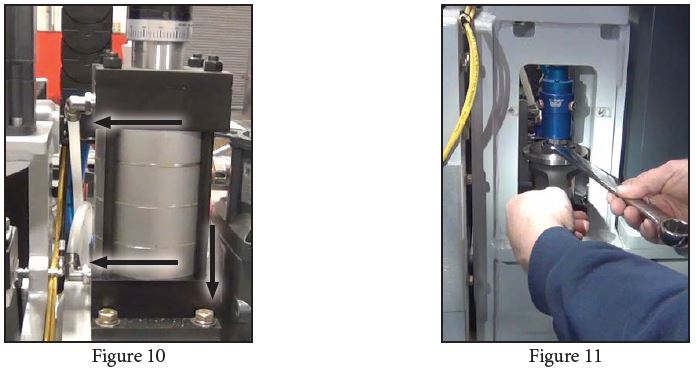
27. Disconnect air lines from the air cylinder. [Figure 10].
28. Use a ¾” socket to remove the air cylinder bolts. [Figure 10].
29. Remove the air cylinder.
30. Use the water union wrench and a 15/16” wrench to remove the water union. [ Figure 11].
31. Using a ratchet extension and rubber mallet to tap the drawbar up until it’s free.
32. Remove the drawbar.
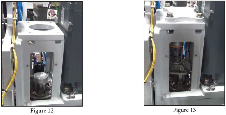
33. Place the aluminum cover on top of spindle. [Figure 12].
34. Install the jack plate using a ¾” socket and the provided bolts. [Figure 13].
35. Place the hydraulic jack inside the housing. [Figure 13]
36. At the bottom of the spindle, remove the silicon seal from the spindle bolts.
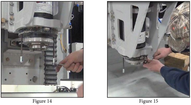
37. The spindle replacement kit includes two threaded rods and jam nuts. Screw the jam nuts on the
threaded rods and Tighten them using two ½” wrenches. [Figure 14].
38. Screw and tighten the threaded rods into the set screw holes on the spindle. [Figure 14].
39. Put safety cable back on, reset any emergency stops, and turn system on.
40. Using the Pendant, lower the spindle (z-axis).
41. Place wood blocks under the spindle for the spindle to rest on.
42. Loosen and remove spindle hex socket head bolts. [Figure 15].
43. If necessary, use the hydraulic jack to separate the spindle from the housing.
44. Remove the jack and the aluminum cover.
45. Using the pendant to raise the spindle housing while carefully removing the spindle away from underneath the housing.
46. Remove the jack plate and clean the housing of any buildup.
Installation Steps
- The spindle replacement kit includes anti-seize, Apply a layer to the housing as shown in figure 16.
- Apply anti-seize to the spindle as shown in figure 17.
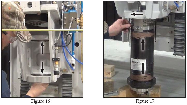
3. Screw threaded rods into the housing’s set screw holes. [Figure 17]
4. Carefully lower the housing over the spindle using the pendant until the threaded rods go through
the spindle holes. Assistance is required for this step.
5. When the housing is low enough, threaded rods will show through the spindle. Screw the provided
nuts to attach and lift the spindle with the housing.
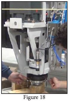
6. Rise the spindle and place a block of wood directly under the spindle. Lower the spindle onto the
block until the spindle is in the housing, it will not be fully seated yet. [Figure 18].
7. Alternately tighten nuts on the threaded rod until the spindle is fully seated.
8. Apply anti-seize to spindle bolts and tighten them. Then remove the threaded rods.
9. The spindle replacement kit includes a silicon seal. After tightening the spindle bolts, apply silicon seal on the spindle bolts.
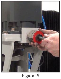
10. Screw the belt tensioner tool in the designated hole. Tighten until the tool touches the mounting plate. [Figure 19].
11. Turn tool about 20 more turns, the tool has a clutch mechanism to prevent over-tightening. The belt should have about 1/8” deflection when properly tightened.
12. Tighten the motor bolts using ¾” socket. Then remove the belt tensioner.
13. Carefully insert the drawbar into the spindle. Install the water union and tighten it using a 7/16”wrench and the water union wrench. Remember that the water union is left-hand thread.
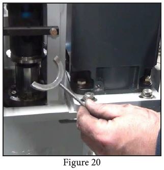
14. Install the air cylinder. Check clearance between spindle and drawbar using the clearance gauge shown in figure 20.
15. Apply a small amount of anti-seize on the air cylinder bolts and tighten them. Reconnect air cylinder air-lines.
16. Install the anti-rotation plate. Use a 7/16” socket to tighten anti-rotation plate bolts.
17. Connect the spindle sensor (Blue wire).
18. Install the fittings on the water union (Top fitting: 10mm hex. Bottom Fitting: 5mm hex) and reconnect the water lines.
19. Install the air fittings on the spindle using 12mm wrench and reconnect the air lines.
20. Install the gripper set. Refer to the gripper set maintenance in the Operation and Maintenance Manual.
21. Install the water ring using 1/2” socket and reconnect the water lines.
22. Replace the shroud and tighten the bolts using 1/4” Hex head socket.
23. Reconnect shroud air lines in the back and turn on shroud air.
24. Reconnect the safety cable.
25. Perform spindle orientation procedure found in the Operation and Maintenance Manual.
It is very important that before running your new spindle with the used tool holders you have completed what is highlighted in the spindle care document. See Spindle Care: https://www.parkindustries.com/service/belt-drive-spindle-care/