Spray penetrating oil on all fasteners a day before starting removal. Clean out Debris in the hex headed bolts before removing
Scan to Read on Device:

Disassembly of Components
Remove the blade and shroud assembly
Fastener locations
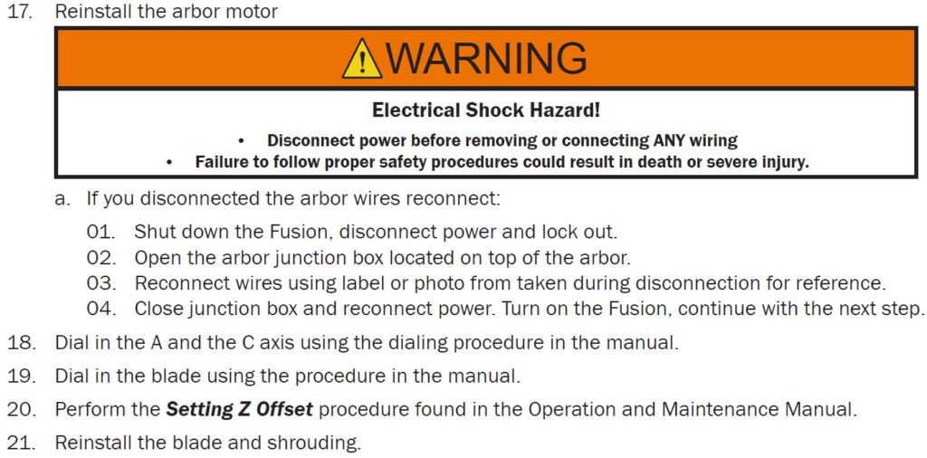
Place a large sheet of cardboard (or other material to help keep parts from falling into the tank) along with two 3CM stone remnants, large enough to support the arbor, on the table directly under the arbor.
Lower the Z axis

Lower the Z Axis until the arbor touches the stones
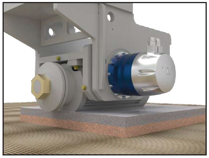
Locating the Fasteners

Remove the 4 bolts that attach the arbor to the miter plate.
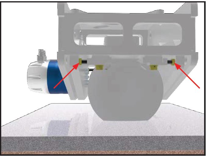
Bolts at rear of Motor
Locate the Jam Nuts
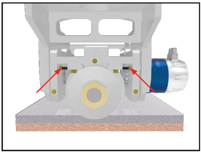
Loosen the jamb nuts then remove the set screw adjusters on the inside of the miter plate, clean or replace
Bolts at rear of Motor. Loosen the jamb nuts then remove the set screw adjusters on the inside of the miter plate, clean or
replace
Servo Mounting Bolts
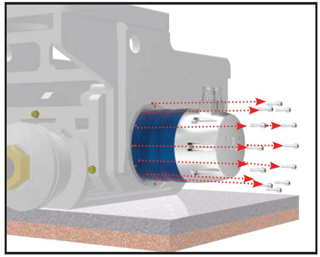
CLEAN OUT THE HEX HEAD BEFORE INSERTING THE HEX WRENCH. If the hex wrench does nut fully insert into the bolt head it will strip out and you will have to cut off the bolt. If you do cut a bolt head you will leave enough length on the threaded bolt end to remove in with a vise grip. Remove the broken bolt by rocking it back and forth slowly until it breaks free after the motor is removed.

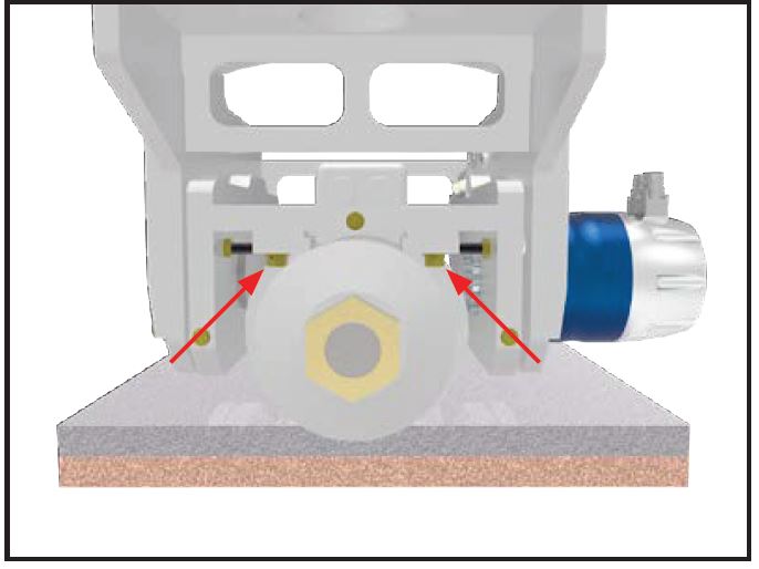
Raising Z axis
Raise the Z axis so you can slide out the arbor to access the inside bolts, use either of the two methods below.
- Unhook arbor power wires
- Shut down the Fusion, disconnect power and lock out.
- Open the arbor junction box located on top of the arbor
- Label or take a photo on how they are connected.
- Remove the wires in the arbor junction box and isolate the wire ends by placing wire nuts on the exposed wire ends. Close the arbor junction box.
- Reconnect power and turn on the fusion, continue with the next step.
- Reconnect power and turn on the fusion, continue with the next step. Angle the arbor a with the wires on it so it will be out of the way to remove the inside bolts.
Protecting Cables
Remove the orange and green cables on the A axis motor and secure them so they will be out of the way
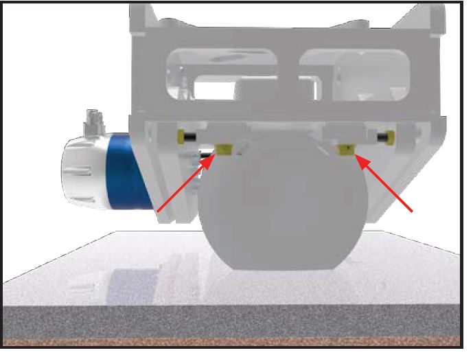
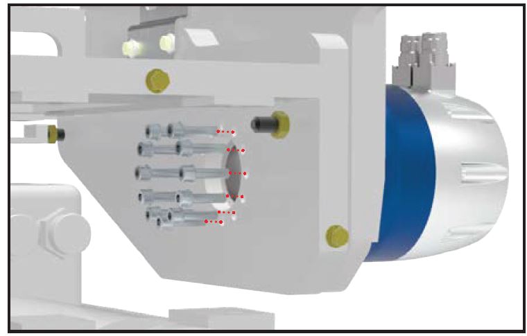
Remove the inside bolts
Remove the inside bolts as you did in step 6, you can cut the heads off of the bolts if needed, cut the bolt half way off and use a hammer to break the head off.
A axis removal
Pull off the A axis motor, if it is stuck in the housing you may need to use a dead blow hammer to break it loose. The miter plate will rotate once the miter motor is removed so you may need to secure this with a strap so it does not tilt.
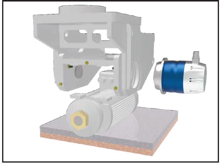
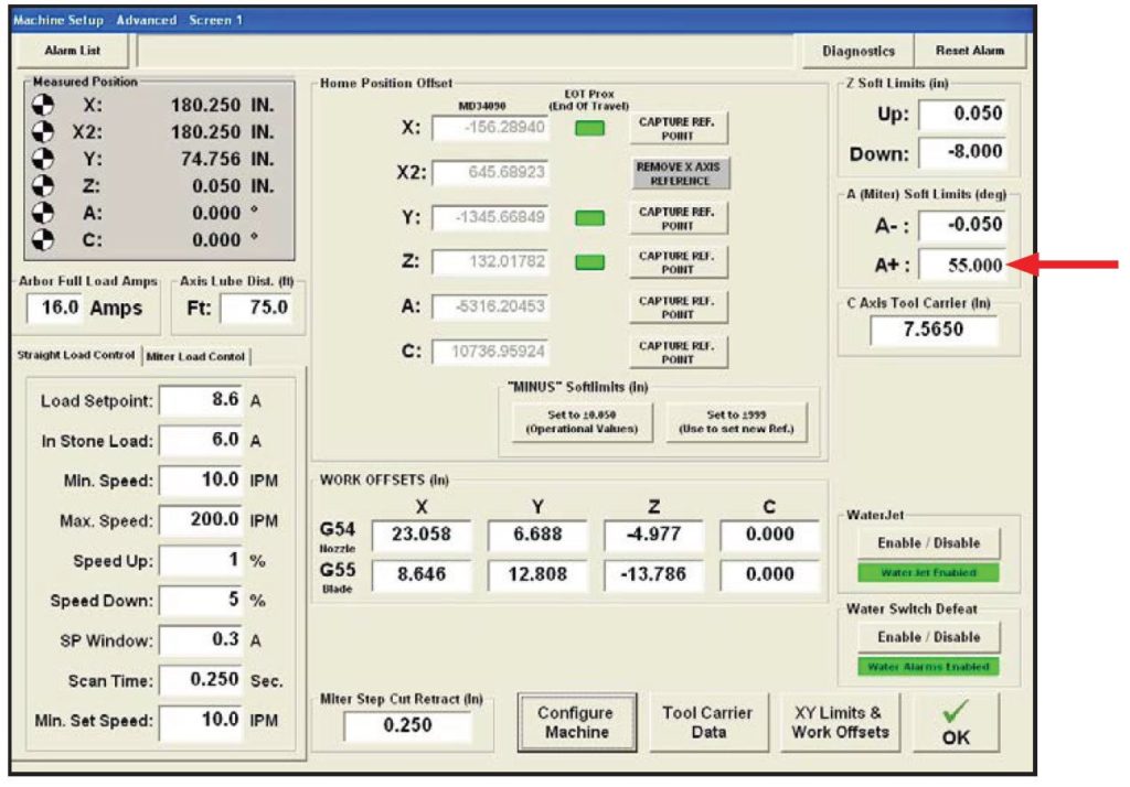
Advanced setup screen
Install the orange and green cables on the motor and set it on the table
Entering the 55 degrees miter limit in the Advanced Screen.
At the operator station open the Advanced Setup Screen 1 and change the A+ miter limit to 55 degrees
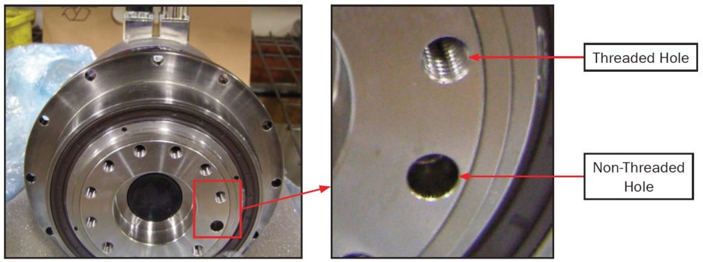
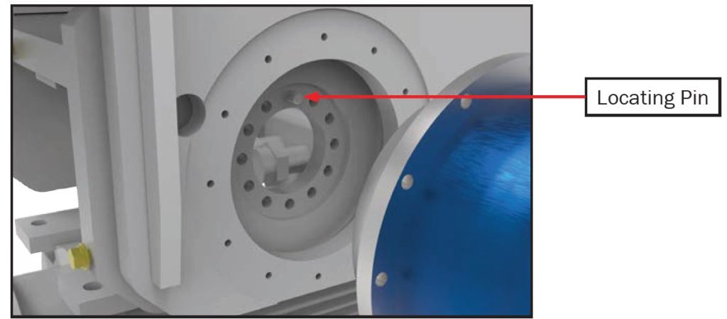
Identifying the locating pin and bolt holes prior to reassembly
Using the pendant move the A axis until non-threaded hole in the servo aligns with the locating pin on the frame of the miter plate (you may have to re-reference a few times by capturing the a reference and powering the machine down and the rebooting then move it again
Tightening the inside bolts using loctite and a torque wrench
Apply thread-locking compound and install the inside bolts, tighten the bolts in a cross pattern (see sequence below) to 25 ft/lbs. (NOTE: #1 in the sequence below will be the locating pin, begin sequence with #2)
Bolt tightening sequence
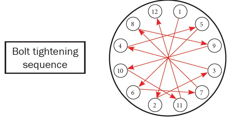
Apply thread-locking compound and install the outside bolts, tighten the bolts in a cross pattern (see sequence below) to 10 ft/lbs.
Adjuster bolts and Jam nuts
Reinstall the adjuster bolts and the jam nuts for the arbor adjustments
Reinstall the arbor motor