
This procedure lists the steps to remove and replace the lifter (rise & fall) screw brass nut in either the Yukon or Jaguar models of bridge saws.
Scan to Read/watch on Device:

Similarities and Differences
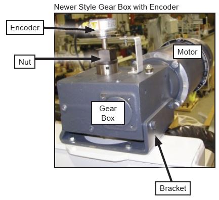
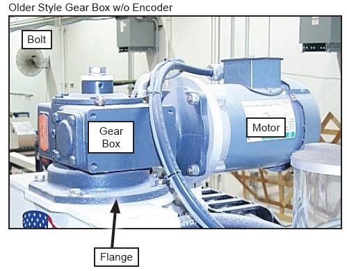
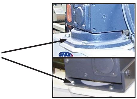
There are two machine models: Yukon and Jaguar. The machine common names are: Yukon, Yukon II, Jaguar II, and Jaguar III. In all machines the lifter (rise & fall) drive system consists of four basic components: motor, gear box, threaded shaft (screw) and nut. The Jaguar III has an encoder connected to the shaft above the gearbox. Motor size does vary from machine to machine, but in all cases the motor is secured to the gearbox via four bolts. There are two gearbox styles. The older style has a mounting flange which is attached to the gearbox and appears as one unit. The newer style has a mounting bracket which holds/cradles the gear box. In both cases the flange or bracket is secured to the lifter (rise & fall) weldment with four bolts.
Starting Point
There are two methods used to secure the threaded shaft (screw) to the gearbox collar. Machines without an encoder use a bolt while machines with an encoder use a nut. In both cases, Loctite® is used in final assembly to secure the nut or bolt to the shaft. If the shaft has to be separated from the gearbox, removing the nut or bolt may be difficult. Tapping the wrench with a dead blow hammer may be needed to loosen. A key step in this procedure is to block up the lifter (rise & fall) assembly. The current operational state of your machine will determine where to position the assembly. If you can still move the lifter (rise & fall) assembly up and down, position it about six inches from the lower limit before starting the blocking process. This allows for easy access to the main components and creates some slack in the wiring
Screw Nut Removal Steps
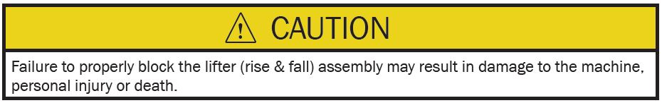
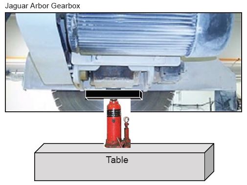
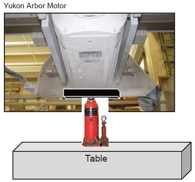
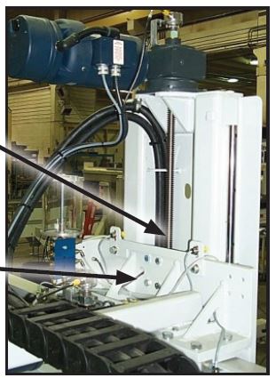
1. Block the lifter (rise & fall) assembly as follows:
a. On a Jaguar, place a two by four (2 x 4) board under the gearbox. On a Yukon, place a two by four (2 x 4) board under the arbor motor, toward the blade end.
b. Place a bottle jack between the board and turn table.
c. Extend the jack until slight upward pressure is applied to the motor or gearbox.
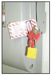
2. Disconnect AC power to the machine. Follow the Lock Out / Tag Out procedures specified by your company.
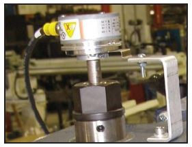
3. If your machine is equipped with an encoder, remove it from the shaft. A collar with a metric Allen screw secures the encoder to the shaft. Use caution when removing the encoder, it is a delicate electronic device which can easily be damaged. DO NOT PRY ON THIS DEVICE.

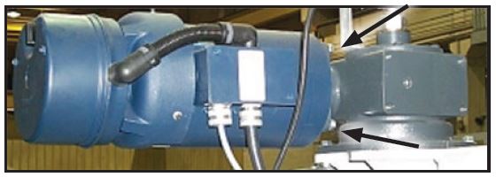
4. Remove the motor from the gearbox (four bolts). It is not necessary to disconnect any of the electric wires. Position the motor on the cross travel or bridge assembly. Be sure to capture the motor shaft key.
5. If the nut has a grease line attached to the side, disconnect it at this time.
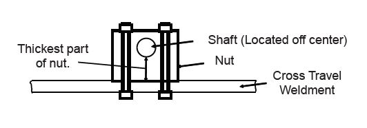
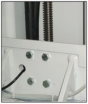
6. Note the orientation of the threaded shaft in the nut (see below) and on which side the grease fitting is located. Remove the bolts (four total) which secure the nut to the cross travel assembly.
7. Remove the bolts (four total) which secure the gearbox (flange or bracket) to the lifter (rise & fall) assembly.
- Remove/lift the entire gearbox, threaded shaft and nut from the machine.
- Remove/unthread the nut from the shaft. Once again note orientation of thick part and grease fitting.
**Threaded Shaft Removal/Replacement Steps (If Needed)**
Removal
- Remove the nut/bolt. Loctite (red color) was used during assembly, a dead blow hammer may be needed to loosen.
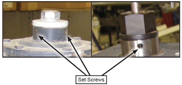
- Loosen the two set screws.
- Remove the shaft. Be sure to capture the key.
Screw Nut Replacement Steps
- Clean shaft and gearbox bore. If necessary, light emery cloth can be used to clean both surfaces.
- Apply anti-seize/lubricating compound to the shaft and bore.
- Align key to keyway and then slide the shaft into the bore, DO NOT force.
- Apply a small amount of Loctite® 271 (red color) or equivalent to the threads of the bolt or nut.
- Replace nut or bolt and then tighten.
- Install the grease line coupling on the new nut.
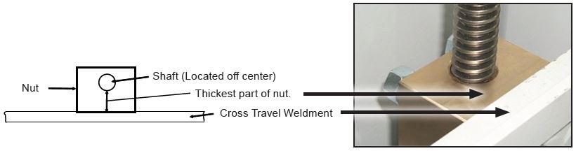
- Install the nut on the shaft, positioning the nut so the thickest part of the nut is toward the cross travel
weldment and the grease line coupling is on the correct side for your machine.
Reinstall the gearbox, shaft and nut assembly onto the lifter (rise & fall) assembly. - Insert the four gearbox bolts. DO NOT completely tighten these bolts. Tighten enough to hold the gear box
in place, but free enough to allow rotation of the nut and unit alignment. - Align the holes in the nut with the holes in the cross travel weldment. Insert the four bolts, install lock
washers and nuts to all four bolts. Tighten the bolts using an alternating pattern to ensure uniform pressure
and proper alignment. - Tighten the four gearbox bolts.
- Reinstall the grease line.
- If the motor was removed, reinstall it. Apply anti-seize/lubricating compound to the shaft and bore.
- Ensure the key and keyway are aligned. Tighten these bolts.
- If an encoder was removed, reinstall it. Apply anti-seize/lubricating compound to the shaft.
- Apply power to the machine. If operator intervention is required to start this machine’s software do so now.
- Move the lifter (rise & fall) assembly to the upper limit. Remove the blocking components.
- Slowly apply three (3) pumps of grease to the nut as the lifter (rise & fall) assembly travels from the upper
limit to the lower limit.