
The overhead laser is a positioning tool used for locating vacuum pods and parts. As the day goes on and shop temperatures fluctuate, the overhead laser accuracy is affected. As much as a half inch of error may be noticed if the laser is not calibrated before each table load of parts.
Scan to Watch/Read on Device:

There are two overhead laser calibration procedures: short and long.
The short method is a Titan program that does a quick fast calibration of the system. A short-cut button to execute the program is found on the Setup screen.
The long method uses a program written by the laser manufacturer to do an extensive calibration. This program is used in two different situations: initial installation and recalibration. During installation a Park Industries associate uses a full set of commands to first physically position the laser in relationship to the table and then to calibrate the laser to reflectors on the table. If the laser is being replaced or the mounting arm was damaged by an overhead crane contract Park Industries Customer Support at (800) 785-3391 for a procedure to align the laser. In the recalibration situation, only a few of the commands are used to calibrate the laser. These are easy to follow steps and can be executed by the user. This sub-section lists the steps to execute the short calibration method and recalibration method using laser manufacturer’s program.
Short Four Point Calibration

1. On the Main Menu screen verify the System is ON
2. Using the pendant, park the cross-travel assembly at the mid-point on the bridge and then move the bridge to far backside of the table.


3. Dampen a soft cloth rag with denatured alcohol and clean the four permanent reflectors. There is a reflector in each corner of the table.

- Setup will bring you to a page which has different setup and configuration options. Once displayed you will need to press the button ‘Calibrate Laser’

6. When the dialog box appears, press ‘Calibrate’
7. Visually verify that the laser checks all four reflectors. The calibration order is front away side, rear away side, front toward side, and rear toward side. There are NO error messages or a successful completion message. If all four reflectors are not checked, clean the reflectors and calibrate again. If all four are checked, the calibration process is complete.
8. On the setup screen press

Long EIGHT point Calibration
Using “SL Laser” Program
As previously stated, the “SL Laser” program is used by a Park Industries associate during installation to completely setup the overhead laser system from scratch. The associate uses a full set of program commands to accomplish the installation tasks. Once properly installed, a sub-set of commands can be use to calibrate the system. The following calibration steps should used after the overhead laser has been properly installed by a Park Industries associate.
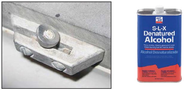
Before Starting This Procedure Clean the four permanent reflectors (each corner of the work table ) using a soft cloth rag dampen a with denatured
alcohol.
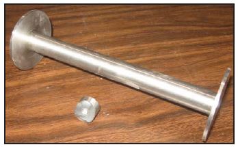
Locate the portable reflector and extension post. Make sure the reflector is cleaned.
1. On the main menu screen verify the System is “on”


2. Using the pendant park the cross-travel assembly at the mid-point on the bridge and them move the bridge to far back side of the table.
- 3. Connect a USB mouse at the external USB port.

4. on the main menu screen close the Titan Software by pressing the EXIT button
5. On the Desktop locate the Auto-SL Icon. The icon is found in the task bar at the lower right corner of the screen


6. Turn off software by right clicking on the icon and then selecting “Close” on the pop-up menu.
7. Locate the SL Teacher icon on the windows desktop.
8. Double click the icon to launch the SL Teacher Software.

9. Verify the SL-Laser Teacher screen shown below appears on the console. The screen has ten (10) tabs. The program normally opens on tab 9 PC Settings, unless there is an established connection. In that case the tab (1) Installation help is the first tab displayed. The PC Setting values were set during installation and do not need to be changed, therefore tab (1) Installation help should be displayed.
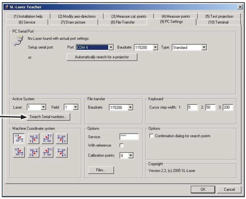
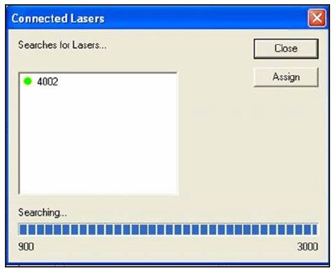
10. Click the search serial numbers button to search for the installed SL laser.
11. The Teacher software will perform a search and should display the serial # of the new laser in the box within 5-10 seconds. This number should match the number on the silver serial # tag located on the outside of the laser.
12. Click the serial number to select it, then click the “Assign” button.

The next steps are used to only to verify the laser is correctly positioned. Once again, this step is used mainly during installation to initially position the laser.

13. Click on (1) Installation Help tab.
14. Select ‘Picture 1″ by clicking on the radio button.
15. Verify that a crosshair appears on the table and is centered. Select “Picture 2” by clicking on the radio button. Verify that the table is inside the rectangle. If the crosshair was not close to the center and/or the table was not inside the large rectangle, contract Park Industries Customer Support at (800) 785-3391 for additional help.

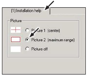
16. For Picture 2 the laser creates/projects a large rectangle. Verify that the table is inside the rectangle
17. The crosshair was not close to the center and/or the table was not inside the large rectangle, contract Park Industries Customer Support at (800) 785-3391 for additional help.
NOTE: The calibration consists of three phases: permanently mounted reflectors, portable reflector only, and portable reflector with extension. The four permanently mounted reflectors are calibrated using Tab 3 – “Measure cal. Points”.
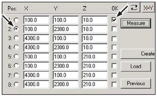
18. Click on the ‘(3) Measure cal.points’ tab

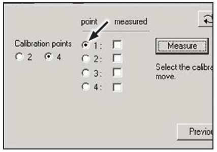
19. Verify that point 1 is selected and the front left permanently mounted reflector is inside the calibration square. If not, drag the box to the location.
20. Press “Measure” button. The laser scans within the square and finds the reflector. When done, three things happen:
• A check mark appears in the measured column,
• Next point is selected
• Calibration square moves to the next corner.

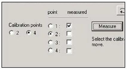
Repeat STEPS 20 for the other three corners making sure they are number as follows: back left is #2, front right is #3 and back right is #4.
21. Once all four points have been measured, the program automatically moves to tab (4) “Measure points”.
22. Verify tab 4 is displayed


23. Verify that POSITION 1 is selected AND the front left hole in the Deck is inside the calibration square
Place the portable reflector stem in the hole and orient the reflector lens (angled side) is facing the overhead laser projector window.

Repeat steps 24 and 25 for the other three corners making sure they are numbered as follows: back left is #2, front right is #3 and back right is #4.
Once all four points have been measured using only the portable reflector, the calibration square moves to the first location and position 5 is selected the table. The portable reflector and extender are use to measure positions 5 through 8.

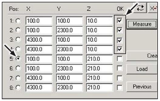
The portable reflector and extender are use to measure positions 5 through 8.
Place the extender with portable reflector in the hole on the table. Ensure the reflector (angled side) is facing the laser. Verify the reflector is inside the calibration square.
Press the ‘Measure’ button
Repeat steps 26 and 27 for the other three Corners they are numbered as follows: Back Left is #6, Front Right is #7, and Back Right is #8.

After position 8 has been measured, a Calibration quality message is displayed on the Tab 4 window. The first number indicates the worst level of accuracy (the value must be less than 1.0) and the number in parenthesis tells at what point it occurred.
Press “OK” button to store the calibration measurements and display Tab 5.
Exit the SL Laser Program by clicking on either the X in the upper right corner OR “Close” button in the lower right corner.

Laser Calibration
- Start the Titan Software from the Menu or from the Desktop Icon


A final check is made using the Titan’s Table Planing and OH Laser screen to verify the overhead laser is projecting an image in the correct location on the table.

7. On the Table Planing and OH Laser Screen, click the ’36’ x ’36’ Square button
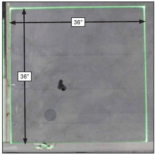
- 8. Measure the rectangle to ensure the laser is projecting the correct size object. Do NOT be concerned if the square is not exacting in the corner. The next procedure adjusts the position. If the square DOES NOT measure 36” by 36”, exit the Titan software, launch the “SL Laser” program and re-execute the calibration steps again.If after recalibration the square does not measure 36” by 36”, call Park Industries Customer Support at (800) 785-3391.
The final check is to fine adjust the laser image position by comparing the project image to an actual cut core hole. This procedure lists the steps to check laser image-to-core hole alignment, determine the offset (if not aligned), and enter offset value to the Titan software.
Only machine operators/users that are proficient at the following should perform this procedure:
• Writing G-Code programs for the Titan
• Storing G-Code programs to the Titan
• Loading material using G-Code Run screen
• Running G-Code programs
- Write a G-Code program to core a single hole in a test piece of material. Position the hole close to the center of the table. Save the program to Titan.
- At the Titan and perform the following:
• Open the G-Code Run screen
• Use “Load G-Code” or “Scan G-Code” button to load the core program
• Press “Main Vac” button if pump is not on
• Press “Laser Projector” button
• Press “Vac Pods” button
• Place Vacuum Pods on table and secure bottom half to table
• Press “Material” button
• Place test piece on pods and secure top half of pods to material
• Press “Float” button
• Square the piece on the pods
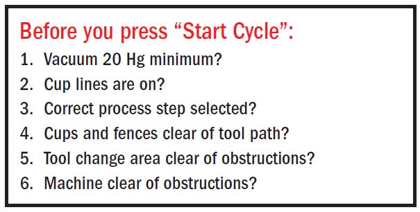
• Press “Float” button - Review the checklist questions and then press “Cycle Start’ button.
- 4. On Run G-code Process screen project the geometry as follows:
• Press “Laser Projector” button
• Press “Geometry” button - 5. Compare the alignment of the laser projected image to the core hole.
• If the laser image and core hole are aligned NO adjustment is required, end of procedure.
• If the laser image and core hole DO NOT align adjustment is required, continue with steps.
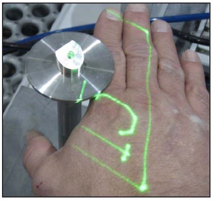
The next step is to determine the adjustment direction (on the X & Y axis) and amount (inches) the laser must be moved to align with the core. Review the example below before executing the step 6.
In the example below the laser image is being projected above and to the left of the core hole. The direction of correction/adjustment for the laser image is negative Y and positive X. The amount of adjustment is determined by measuring the distance between the edges of the laser image and the core hole. These are labeled as Y Offset and X Offset in the
example. If Y Offset was 0.25 inches and X Offset was 0.375 inches the adjustment values are: Y = – 0.25 and X = +0.375

- 6. Using a straight edge determine the direction and amount of adjustment needed to position the laser image over the core hole. Record the values below:
- Y Offset: Amount – _____ inches Direction – Negative or Positive
- X Offset: Amount – _____ inches Direction – Negative or Positive
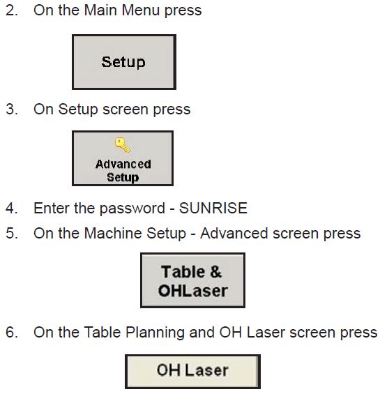
- 7. From the Run G-code Process screen move to the Table Planning and OH Laser screen as follows:
• On Run G-Code Screen press “Main Menu” button
• On the Main Menu press “Setup” button
• On the Setup Screen press “Advanced Setup” button
• On the keyboard enter password of SUNRISE (all caps)
• On Machine Setup – Advanced screen press “Table & OH Laser” button
• On the Table Planning and OH Laser screen press “OH Laser” button

- 8. From Table Planning and OH Laser screen enter current
- • Table – Laser Y Adjust value here (include sign) _______
- • From step 6 enter the Laser Y Offset value (include sign) ____________
- • Add numbers for new Table – Laser Y Adjust value (include sign) _______
- 9. From Table Planning and OH Laser screen enter current
• Table – Laser X Adjust value here (include sign) _______ - • From step 6 enter the Laser X Offset value (include sign) ____________
- • Add numbers for new Table – Laser X Adjust value (include sign) ______
- 10. Tap the Table – Laser Y Adjust readout to display a numeric keypad and then enter the new value calculated in step 8.
- 11. Tap the Table – Laser X Adjust readout to display a numeric keypad and then enter the new value calculated in step 9.

- 12. Return to the Run G-code Process screen as follows:
• On the Table Planning and OH Laser screen press “OK” button.
• On Machine Setup – Advanced screen press “OK” button.
• On the Setup Screen press “Main Menu” button.
• On the Main Menu press “G-Code Process” button. - 13. On Run G-code Process screen load the Core Hole Test program, if not currently loaded.
- 14. On Run G-code Process screen project the geometry as follows:
• Press “Laser Projector” button.
• Press “Geometry” button. - 15. Check the laser image to core hole alignment.
• If results meet user’s requirements, this procedure is done. if additional adjustment is needed repeat steps 6 thru 15.