
This guide is how to maintain and service the smart spindle drive assembly
Scan to Read on Device:

SKILL LEVEL 2

ESTIMATED TIME TO COMPLETE: 1 HOUR
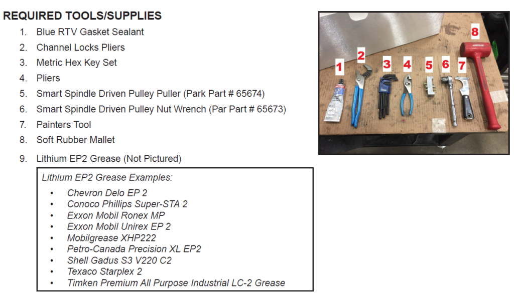
Tools Needed
Position Machine for easy of access
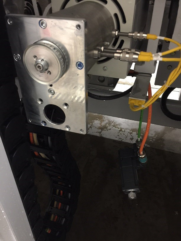
From the manual screen on the operators panel, position the miter angle of the bridge roughly at 90 degrees. Does not need to be exact. Once bridge is positioned, power down the machine, use your shop lock out/tag out procedure to secure machine from movement. Then open rear folding doors to access the smart spindle.
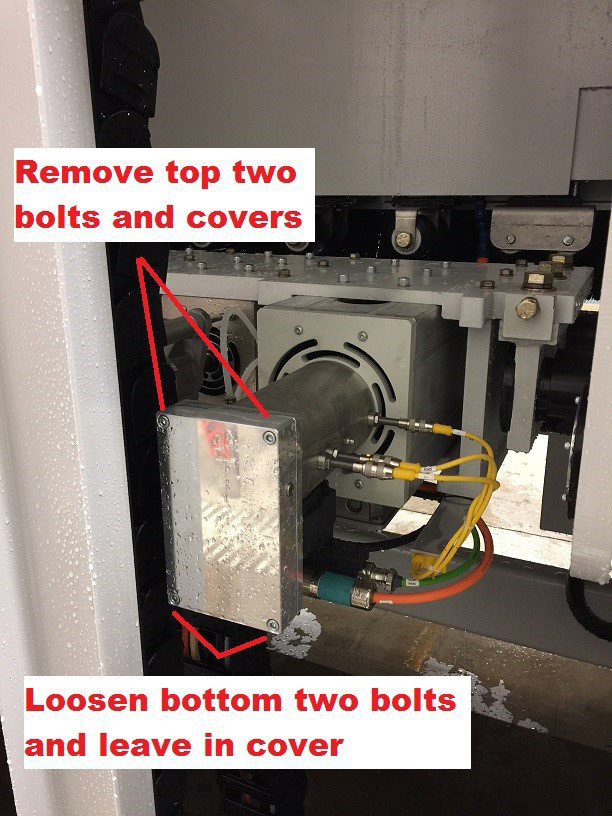
Remove top two bolts from belt cover and loosen bottom two with 5mm hex key
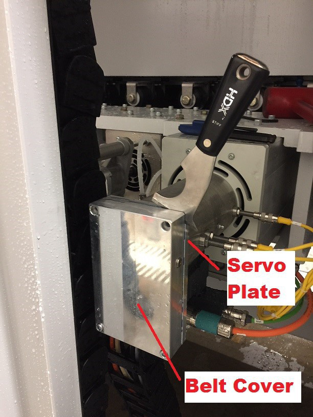
Using painters tool pry off cover carefully. Insert sharp edge of tool between cover and servo mounting plate. If needed gently tap end of handle with soft mallet or small hammer to act as wedge. After cover comes loose remove bottom two hex head bolts while supporting cover from falling. When removing cover inspect for water intrusion. Look for actual water or condensation inside. Carefully remove cover o-ring, clean belt cover and servo plate with clean painters tool and then set belt cover / cover o-ring aside for re-assembly. (Photos below)
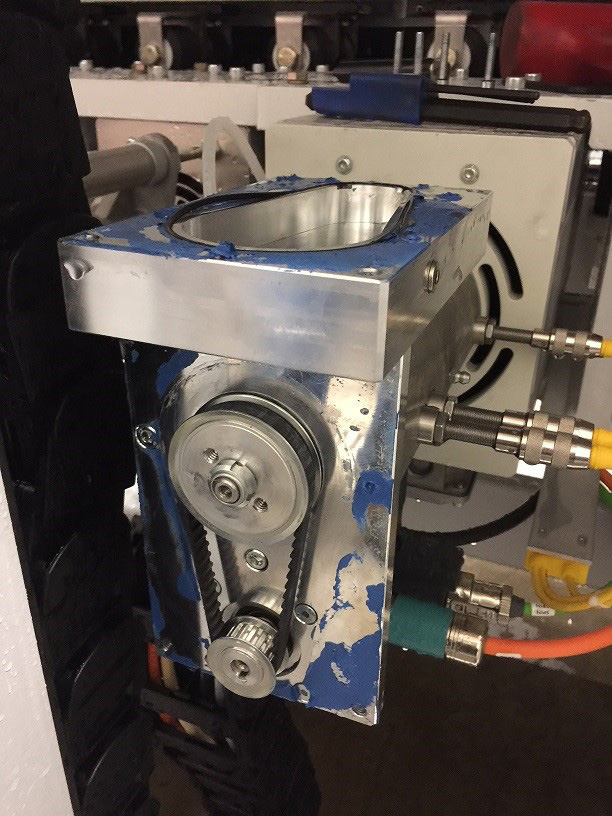
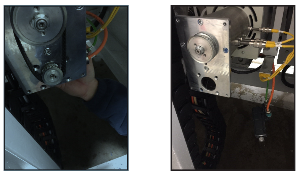
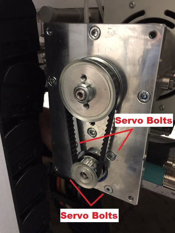
Remove four servo motor bolts using 3mm hex wrench and 3/8” wrench for holding nut on rear of servo flange. Then tilt servo motor, remove belt and slide servo out of mounting plate. Easily lower servo motor and let hang by power/encoder cables. (Photos below)

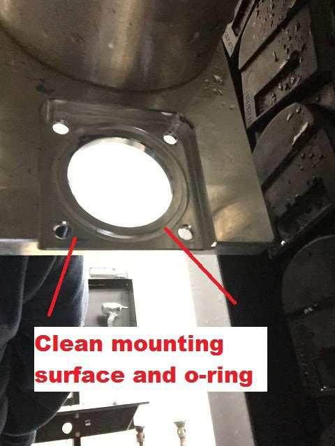
Locate servo flange o-ring and carefully clean and set aside for re-assembly. Then clean servo mounting plate surface shown in photo below.
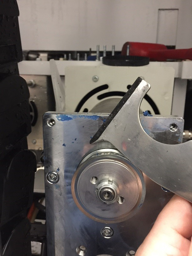
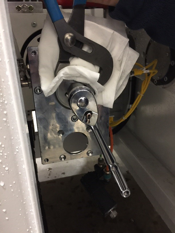
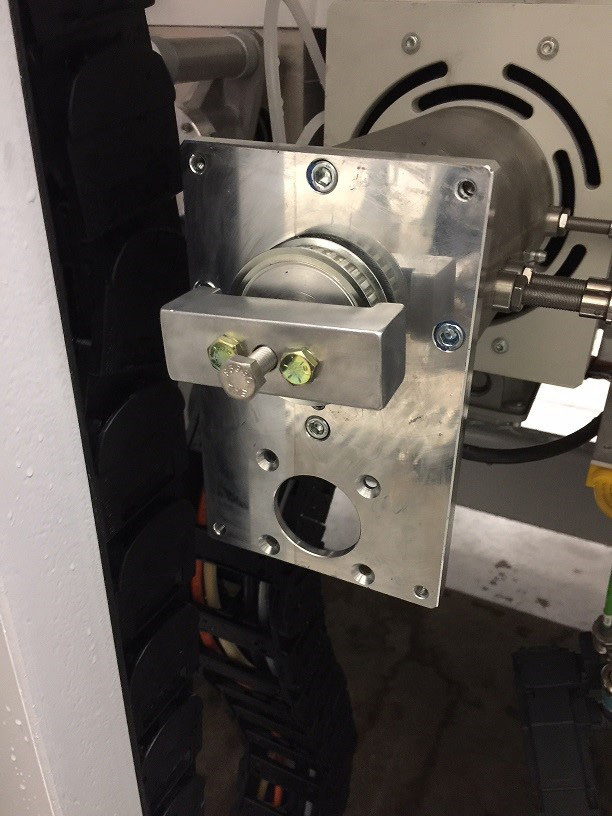
Using spanner wrench (#65673) and 3/8” ratchet remove nut from driven pulley. Use cloth between driven pulley and channel locks to protect driven pulley while loosening spanner nut.
Remove driven pulley with driven pulley puller (#65674). Install 1/4-20 x 1 1/4” bolts through outside puller holes and thread into pulley. Then install 5/8-18 x 1 1/4” bolt in threaded center puller hole and slowly tighten to pull pulley off.
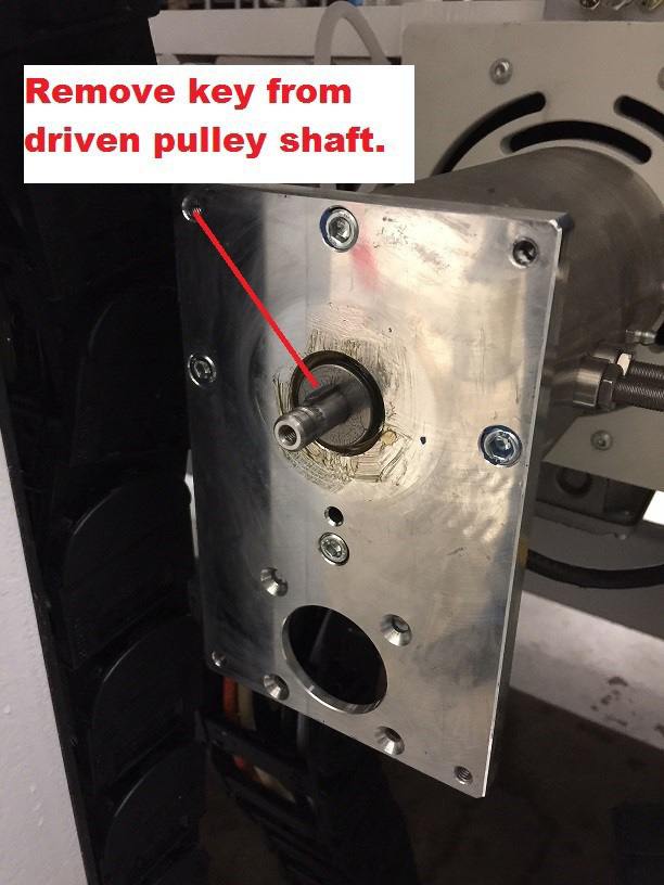
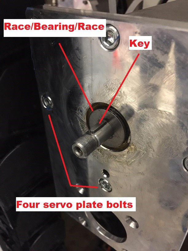
Carefully Remove key from driven pull shaft with pliers. Key is small so use a second hand to try to keep key from falling to ground.
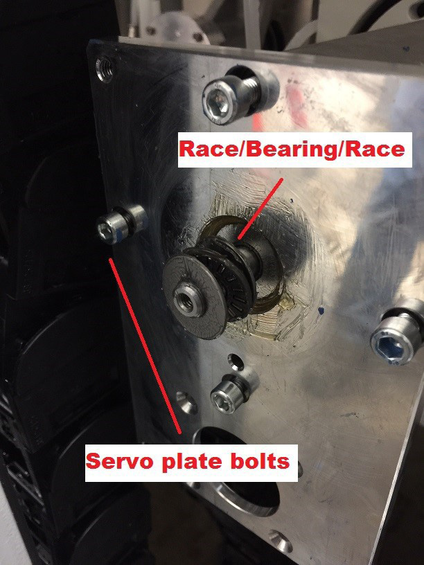
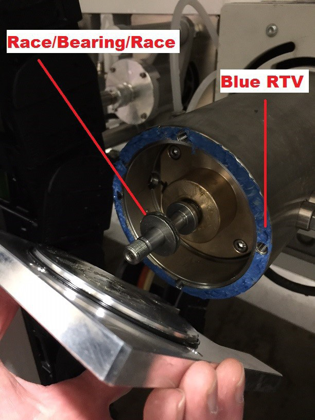
Loosen the four servo mounting plate bolts with a 5mm hex key wrench then slowly slide forward and then back to expose two races and bearing for removal. Remove race/bearing/race and then remove four servo plate mounting bolts and slide plate off of drive screw. When removing pay attention to rear of servo plate as second set of races bearings maybe sticking to plate as not to lose them.
Clean rear of servo plate and servo plate o-ring thoroughly and set aside.
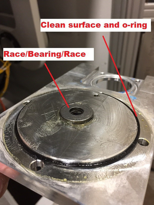
If second set of race and bearings remain behind remove them now and set aside for re-assembly.
Inspection of Internal COmponents
Using your index finger and thumb rotate the drive screw clockwise and counter clockwise several revolutions. Drive shaft screw should turn easily in both directions. If not call Park Industries Customer Service for further instructions.
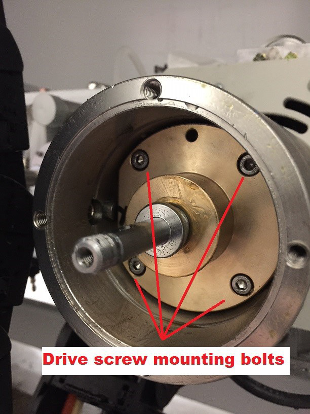
If inspection fails then removal of drive screw will be required by removing drive screw mounting bolts as seen in photo below.
Inspect spindle housing for contamination / moisture. If all is clean proceed to reassembly. If not try to locate source of contamination and/or moisture and remedy or call Park Industries Customer Service.
Inspect the drive screw shaft bushing in the servo mounting plate. When drive screw is installed through the servo mounting plate there should be no play when lifting up or pushing down on drive screw shaft. Lubricate bushing with lithium EP2 grease during reassembly.
Re-assembly of parts
CLEAN ALL PARTS THOROUGHLY. This is crucial for proper re-assembly and internal component protection. Both surfaces of the servo mounting plate must be free of gasket making material, grease and is dry. Clean mounting face of belt cover and it too should be completely free of gasket material, grease and is dry.
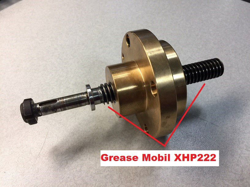
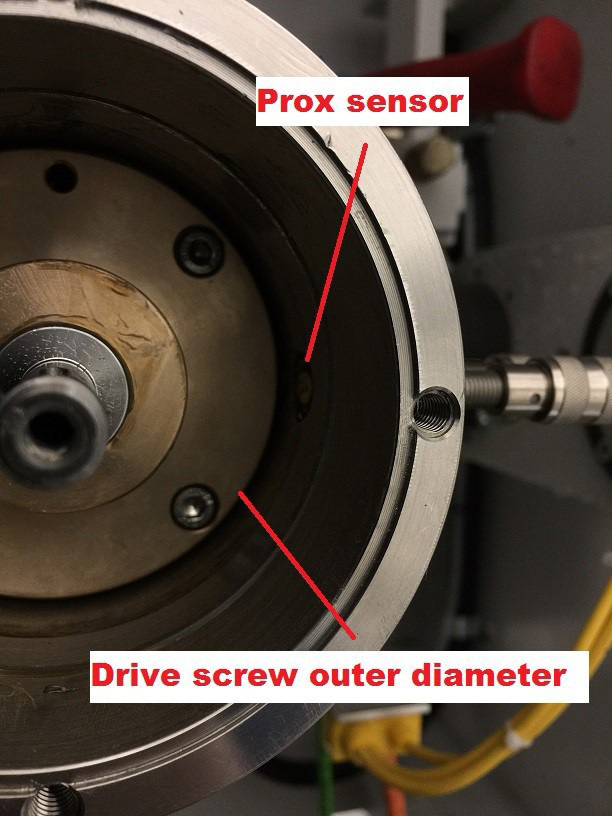
If drive screw has been removed apply a small amount of Lithium EP2 grease to the threaded portion of the drive screw. Install drive screw with flat side of brass nut facing opposite of the proximity sensors (or stated another way, flat side aligned with key way on side of housing) and install four hex head mounting bolts. NOTE: Now is a good time to install new proximity sensors or adjust existing proximity sensors for proper depth. See step #19
Optional- for adjusting proximity sensors – Slide largest diameter of round brass part of drive screw in front of each proximity and loosen jam nut and slowly thread in proximity until proximity just touches brass nut. Then back out proximity 1/4 turn and lock jam nut. Repeat for each proximity sensor.
Install races and thrust bearings on to drive screw shaft. Installation should be race/bearing/race. Coat bearing, races, and smooth part of the drive shaft screw with Lithium EP2 grease when installing.
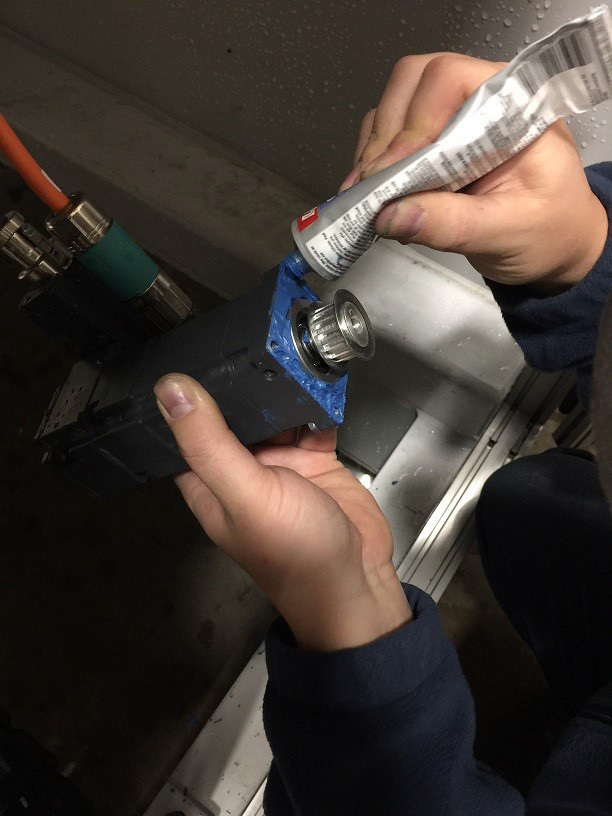
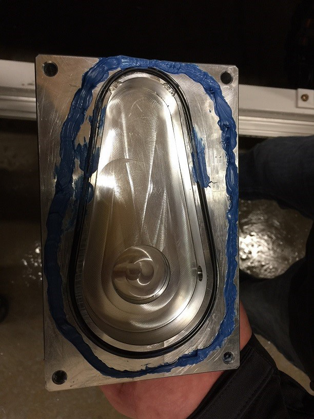
Apply blue RTV to surface spindle tube.
Slide servo mounting plate on to drive screw and pay attention to orientation. Recessed servo mounting surface should be toward conveyor. Install and tighten four hex head mounting bolts.
Install races and thrust bearings on to drive screw shaft. Installation should be race/bearing/race. Then install pulley key. Coat bearing and races with Lithium EP2 grease when installing.
Install driven pulley and thread on driven pulley nut.
Slowly tighten nut until all end play is eliminated and drive screw turns easily with index finger and thumb. Pulley should be as free as possible with no play when pushing/pulling driven pulley toward and away from spindle body.

Install servo o-ring and apply blue RTV to servo mounting surface and to flange of servo motor. Make sure bolt mounting holes in servo plate are closed with blue RTV.
Slide in servo at slight angle and install belt on driven pulley and servo pulley. Then straighten out servo and seat in to servo plate mounting surface.
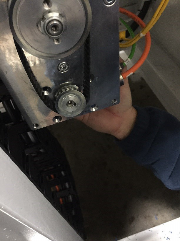
Install the servo motor four hex head mounting bolts and nuts and tighten.
Apply generous amount of blue RTV to belt cover mounting surface and install cover/bolts. FOLLOW MANUFACTURER INSTRUCTIONS ON APPLICATION AND CURING TIME TO ENSURE PROPER SEAL.
RTV SHOULD CURE OVERNIGHT. FAILURE TO DO SO CAN LEAD TO WATER INTRUSION AND SERVO FAILURE.
Remove lock out / tag out and power up machine. NOTE: Once machine is powered up, be sure to reset your tool wear setting!