
A step-by-step guide on replacing the drawbar activator. The new drawbar gives
easier access to the water union. Newer style drawbar activator part number is 102672
Scan to View on Mobile Device

You can download a printer friendly PDF version here:
Tools and SUpplies:
- ½” Socket
- 7/8 wrench
- Pry bar
- Shop towels
- 1 1/8″ Socket
- 10mm Hex Wrench
- Metaflux Spray PN# 3400037
- 3/4″ Socket
- 7mm Hex Wrench
- Loctite 243
Press the e-stop and shut off the main air and water.
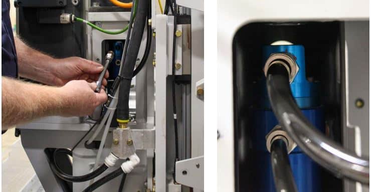
Remove the water lines, then fittings. A 10mm hex for the top fitting and 7mm hex for the bottom.
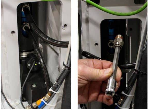
Remove the air lines leading to the air cylinder.
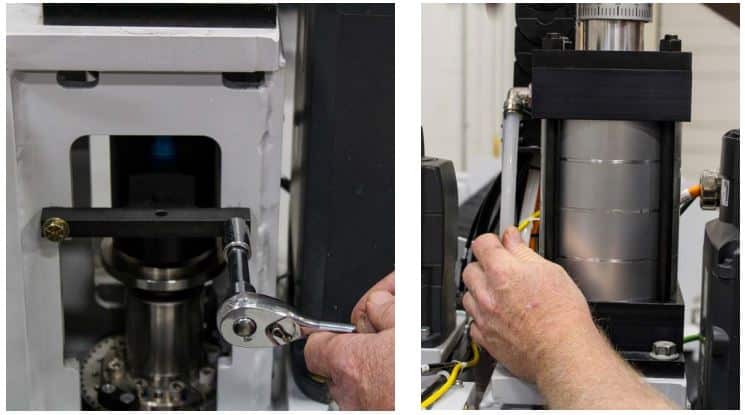
Remove the anti rotation bracket with a ½” socket
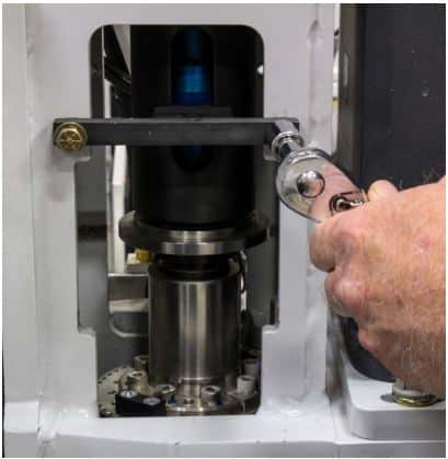
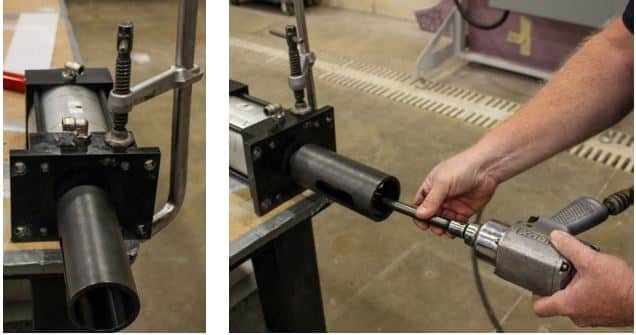
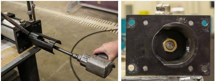
Remove the 4 bolts with a ¾” socket, then lift out the air cylinder.
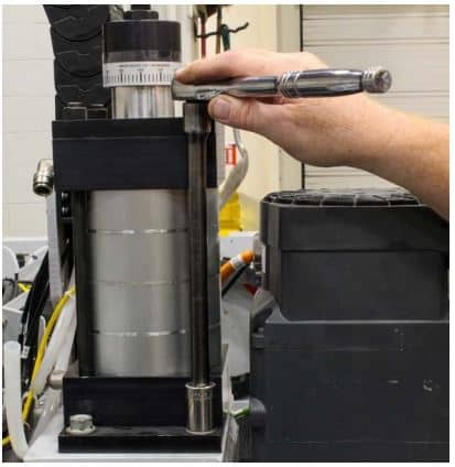
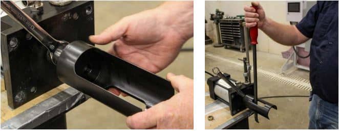
Affix the air cylinder to a bench using a clamp, then remove the 1⅛” nut from the air cylinder rod.
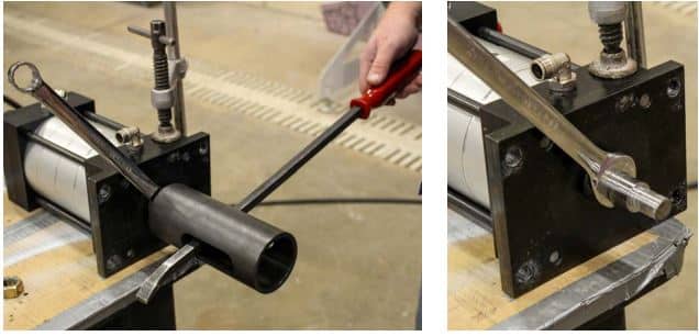
Use a pry bar and a ⅞ wrench to remove the drawbar activator
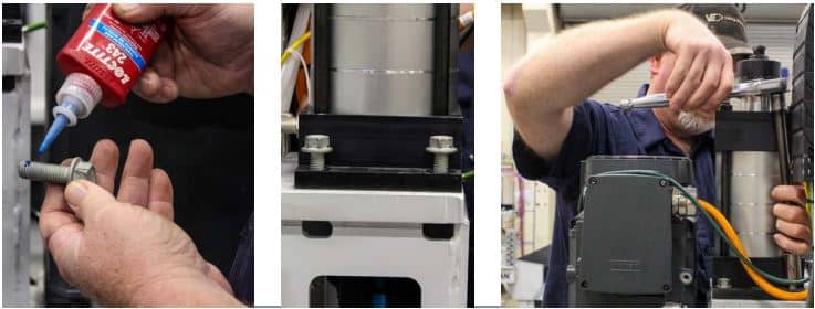
9. Apply Loctite 243 to the threads.
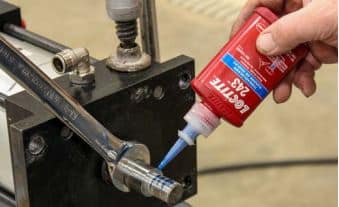
Screw on the new drawbar activator. Use a pry bar to tighten.
Screw the nut onto the air cylinder rod.
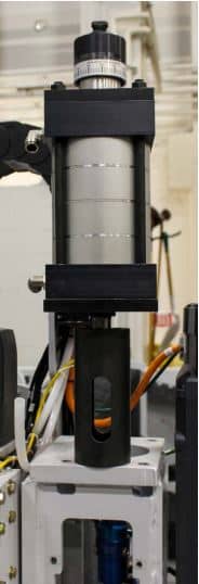
Cycle air through the air cylinder and adjust the drawbar activator so the air cylinder’s micro adjust repair opening faces right (when installed), squaring the drawbar activator’s cutout with the cylinder base (ref. drawing).
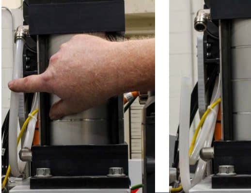
Reattach the air cylinder to the spindle mount. Confirm the air-cylinder gap (see link below).
Apply Loctite 243 to the 4 bolts, hand screw them in, then tighten them with a ¾” socket wrench.
Reattach the anti rotation bracket back. Hook up the air line to the air cylinder
Reattach the fittings to the water union, then the water lines to the fittings.
Turn the water and air back on.
Check for air and water leaks.
You will need to capture your new drawbar extend and retract numbers.
You can find the video and document here for setting up your drawbar extend and retract.