Fastback travel block replacement.
Scan to Read on Device:

removal
Power off machine and Lock Out Tag Out.
If removing Hold Down Assembly take photos to document location of air lines and all power/communication cables. Then disconnect all air/water lines, and power/communication cables. If just gaining access to travel blocks Go To Step 3.
Move hold down assembly in until all four chain cover bolts are aligned (outfeed side is same as in feed side) as seen in Figure 1.1 and 1.2
Remove four socket head cap screws from chain cover. There are two on feed side and two on out feed side.
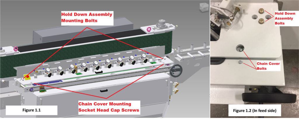
Remove hold down adjustment hand wheel from drive screw on in feed side. Then remove chain cover.
Remove chain using master link.
Now remove four bolts mounting hold down assembly to travel blocks. Two in feed and two outfeed See Figure 2
Carefully support hold down assembly and lift up while feeding all cables and lines down through hold down assembly and secure to gain access to travel block assembly hold down mounting bolts and support to prevent falling or remove completely.
Now remove eight bolts securing travel block assembly to main frame and remove . See Figure 2.
Repair/replace travel block assemblies and reinstall is reverse of removal.

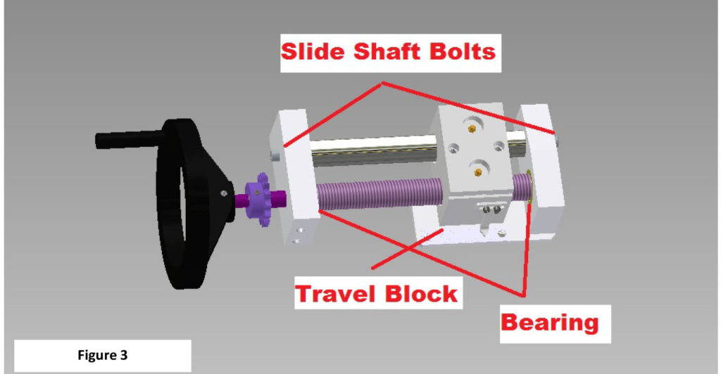
Remove Slide Shaft Bolts and separate from mounts and unthread travel block. Inspect, clean, repair and reassemble. See Figure 3
installation
Place travel blocks into original position and install eight travel block mounting bolts and tighten. See Figure 3
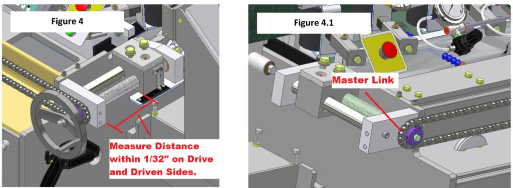
Next adjust travel blocks and take measurement and keep measurement within 1/32” between both travel blocks. See Figure 4

This process will work best with two people. Wrap chain around driven sprocket so center of master link will be in about the 9:00 o’clock position and then wrap chain around drive sprocket and back to driven sprocket while maintaining measurement taken in step 2 and install master link. See Fig. 4.1
Install hand wheel and drive travel blocks in and out and take measurement again to maintain accuracy and remain within the 1/32” tolerance.
Lift and remove support blocks from under hold down assembly and carefully lower down onto travel blocks while aligning travel block mounting holes with mounting holes in hold down assembly and install four mounting bolts. See Figures 5 and 5.1
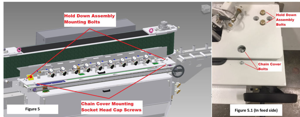
Install chain cover and hand wheel. Adjust hold down assembly with hand wheel to align chain cover bolt access holes and then install chain cover mounting bolts. Re-install any hoses and cables that were removed. See Figure 5.1
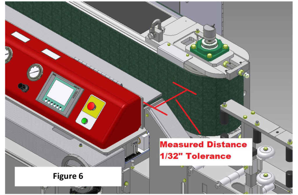
Take measurement from belt to rear of hold down assembly on in feed and out feed sides with a tolerance of 1/32” and adjust hold down assembly until with in tolerance and tighten four hold down assembly mounting bolts. See Figure 6
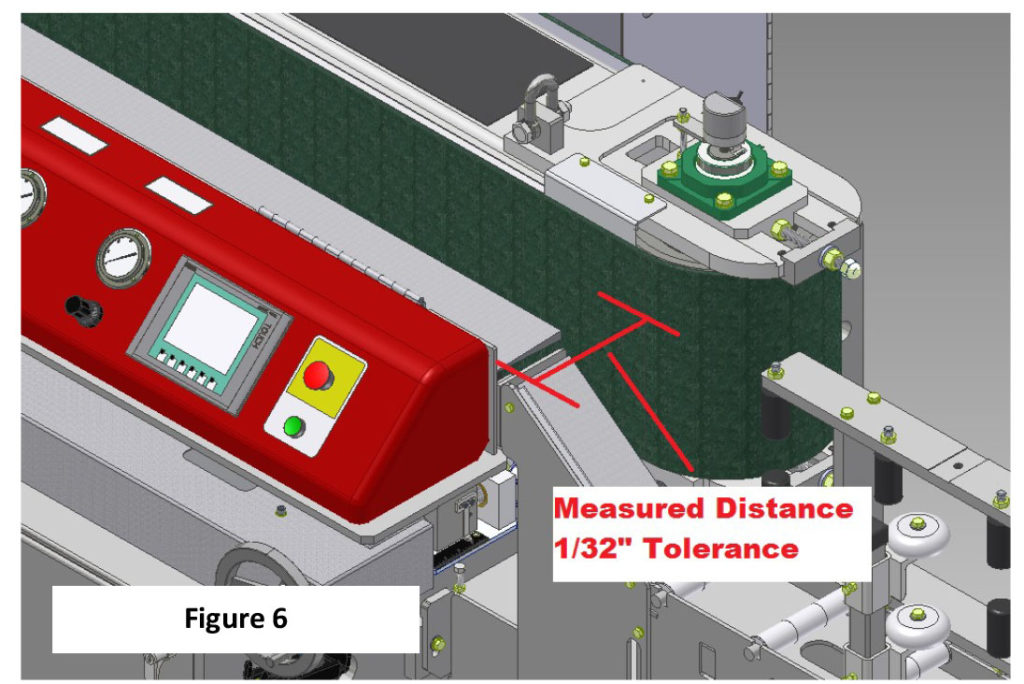
Insert aluminum bar into machine and tighten until hold down rollers compress and leave a 1/8” gap between washer and rear of hold down roller housing. See Figure
Adjust measurement indicator to 3/4” See Figure 6
Power up machine and run test piece to assure machine is operating correctly.