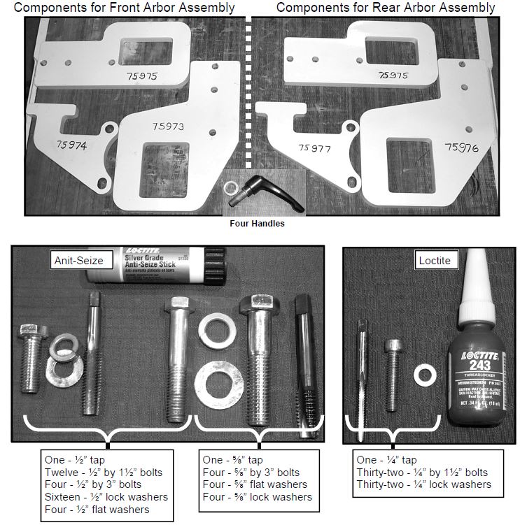
Your kit should contain the parts illustrated below. If the kit is missing any of these parts DO NOT start this procedure, contact Park Industries Customer Service at 1-800-498-5687.
Scan to Read on Device:

Confirm components are correct per the kit part numbers
Rear Arbor Assembly Retainer steps

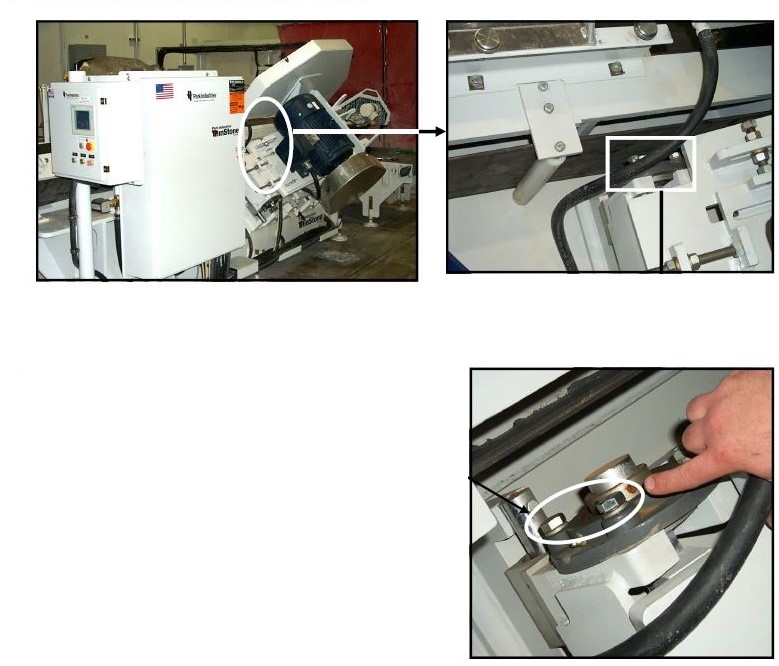
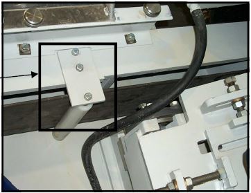
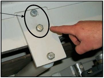
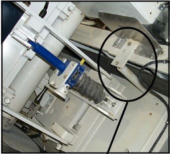
Locate the upper arbor motor mounting plate pivot bearing.
Remove the two bolts closest to the front of the machine. Note the size (diameter of this bolt). Older units used 1/2″ bolts while newer units used 5/8″ replacement bolts. The retainer kit contains both 1/2″ and 5/8″ replacement bolts.
Locate the front conveyor belt guide roller bracket.
Remove the two bolts which secure the roller mounting bracket to the frame.

Remove the bracket and roller
Remove the bolt which secures the roller shaft to the bracket


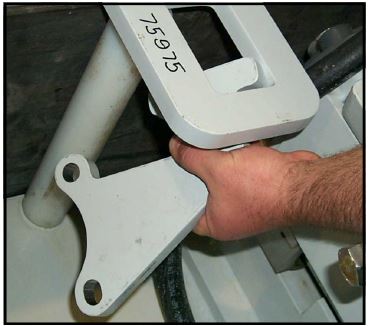
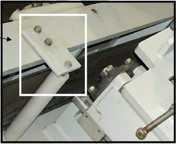
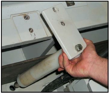
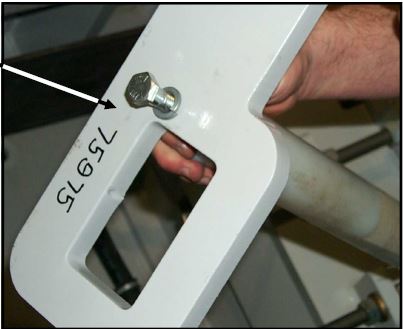
Locate the new 75975 mounting plate. Position the mounting plate as shown in this picture. Using a ½” by 1½” bolt (coated with antiseize) and lock washer secure the roller shaft to the mounting plate.
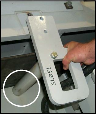
Position the roller bracket on the machine. Ensure the roller shaft is inserted into the hole on the frame.

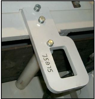
Secure the mounting bracket to the frame. Use two ½” by 1½” bolts (coated with anti-seize) and lock washers.
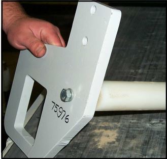
Locate the 75977 assembly.
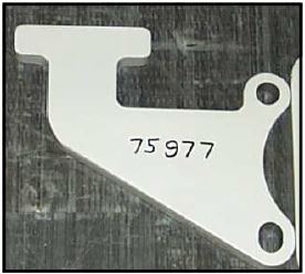
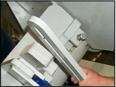
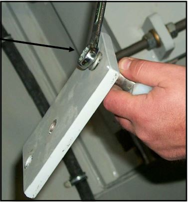
Orientate the assembly as shown in this picture.
Rotate the part into position. Ensure the “T” portion extents through the rectangular hole in the mounting bracket and . . . .
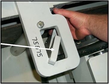
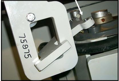
The mounting holes align with holes in the bearing.
Using two ½” by 3” bolts (coated withanti-seize) for older machines or 3” by 3” bolts (coated with anti-seize) for newer machines with flat and lock washers, secure the assembly to the arbor motor mounting bracket.
On the screw jack side of the arbor assembly locate the rear main conveyor belt roller guide assembly.
Remove the two screws which secure the bracket to the frame and then remove the entire assembly.

Remove the bolt with secures the roller shaft to the bracket.
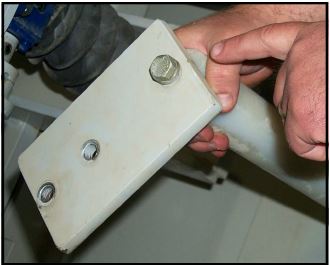
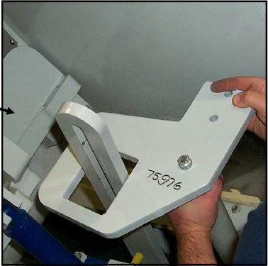
Locate the new 75976 mounting plate.Position the mounting plate as shown in this picture. Using a ½” by 1½” bolt (coated with antiseize) and lock washer secure the roller shaft to the mounting plate.

Remove the top/upper depth adjustment clamp.
Allow for enough adjustment to accept the new parts.
Position the roller bracket on the machine. Ensure the roller shaft is inserted into the hole on the frame.
Make sure end of Roller Shaft is inserted into the frame
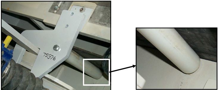

Secure the mounting bracket to the frame. Use a ½” by 1½” bolts (coated with anti-seize) and lock washers.
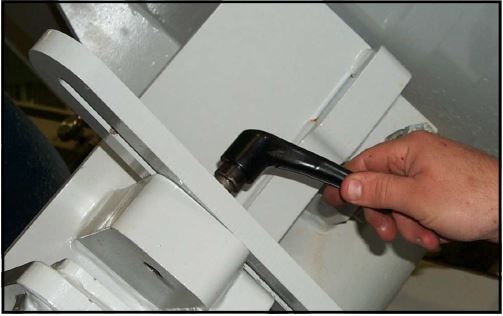
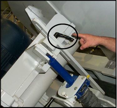
Position the depth adjustment support bracket and then install a new clamp handle (coated with anti-seize).
NOTE: New locking handles are supplied in this kit if yours are seized or damaged. It is very important to ensure they can rotated freely at all times. During weekly maintenance, rotate each handle even if adjustments are not being made.
Front Arbor steps: Begin here
Front Arbor Assembly Retainer Kit
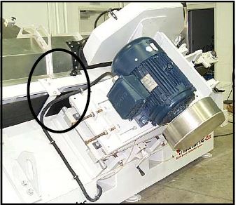
Locate the upper arbor motor mounting plate pivot bearing
Remove the two bolts closest to the rear of the machine. Note the size (diameter) of this bolt. Older units used 1/2″ bolts while newer units used 5/8″ bolts. The retainer kit contains both1/2″ and 5/8″ replacement bolts.
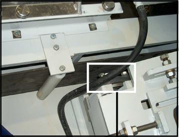
Locate the conveyor belt guide roller bracket.
remove the two bolts which secure the roller mounting bracket to the frame

Remove the bracket and roller
Remove the bolt which secures the roller shaft to the bracket
Locate the new 75975 mounting plate. Position the mounting plate as shown in this picture. Using a 1/2″ x 1 1/2″ bolt (coated with anti-seize) and lock washer secure the roller shaft to the mounting plate.
Position the roller bracket on the machine.
Ensure the roller shaft is inserted
into the hole on the frame.

Secure the mounting bracket to the
frame. Use ½” by 1½” bolts (coated with
anti-seize) and lock washers.
Locate the 75974 assembly.
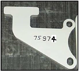

Orient the assembly as shown in this
picture.
Rotate the part into position. Ensure the “T” portion extents through the rectangular hole in the mounting bracket and …


The mounting holes align with holes
in the bearing.
Using two ½” by 3” bolts (coated with
anti-seize) for older machines or 3” by 3”
bolts (coated with anti-seize) for newer
machines with flat and lock washers, secure the assembly to the arbor motor
mounting bracket.


On the screw jack side of the arbor assembly locate the front main conveyor belt roller guide assembly
Remove the two screws which secure
the bracket to the frame and then remove
the entire assembly.

Remove the bolt with secures the roller
shaft to the bracket.
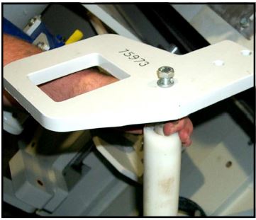
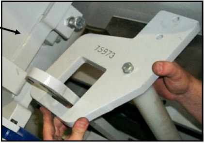
Locate the new 75973 mounting plate.
Position the mounting plate as shown in
this picture. Using a ½” by 1½” bolt (coated with antiseize) and lock washer secure the roller shaft to the mounting plate.
Remove the top/upper depth adjustment
clamp.
Pivot the support arm away from the motor
and then . . . . . . . .
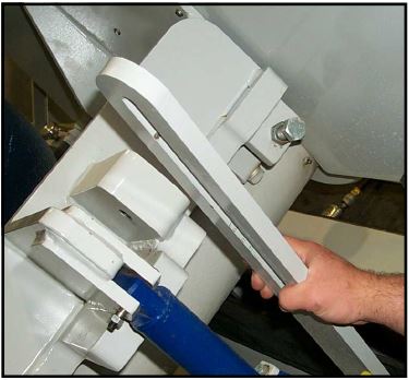
Slide the 75973 assembly over the support arm. Orientate the assembly as shown in this picture. Position the roller bracket on the machine. Ensure the roller shaft is inserted into the hole on the frame
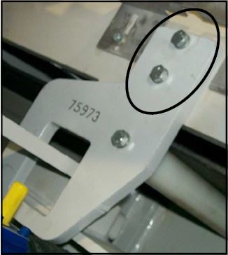
Secure the mounting bracket to the frame. Use two ½” by 1½” bolts (coated with anti-seize) and lock washers.
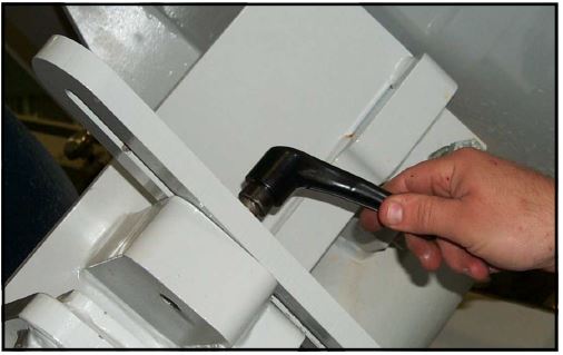
Position the depth adjustment
support bracket and then install
a new clamp handle (coated
with anti-seize).
NOTE: New locking handles are supplied in this kit if yours are
seized or damaged. It is very important to ensure they can rotated
freely at all times. During weekly maintenance, rotate
each handle even if adjustments are not being made.

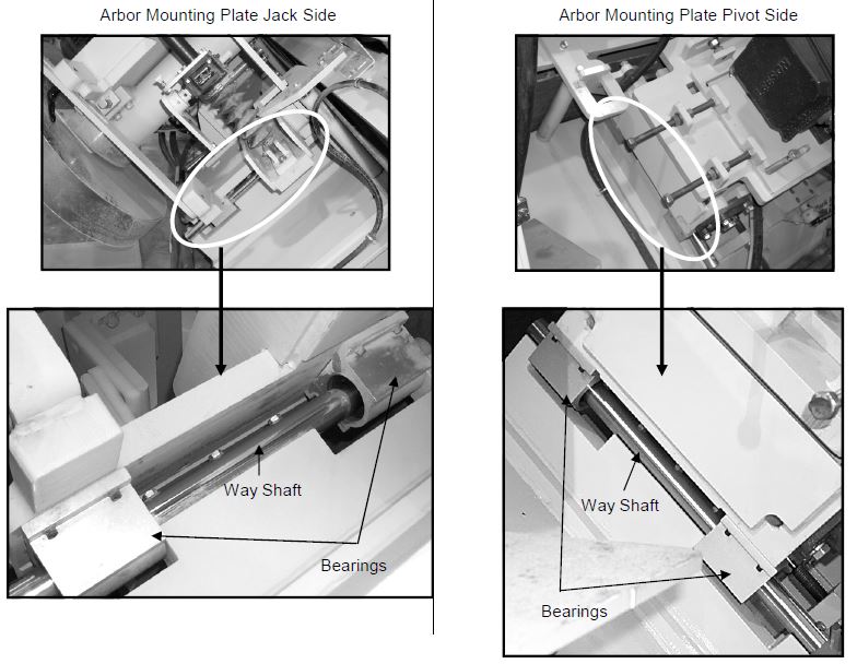
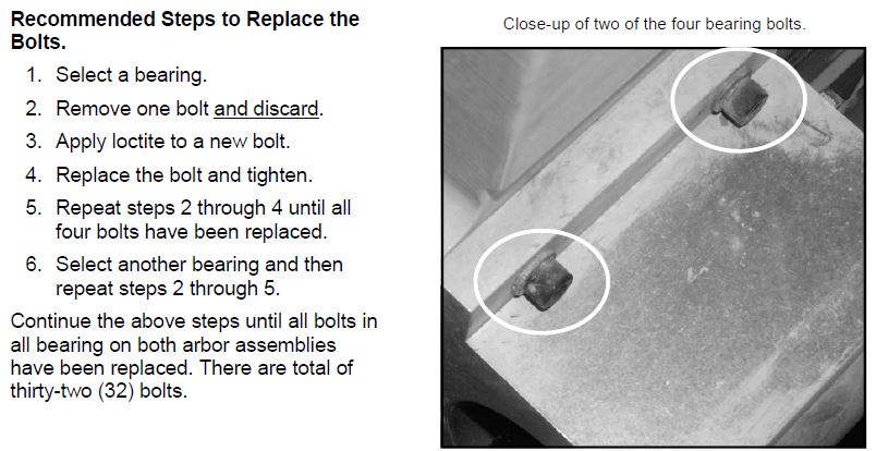
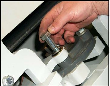
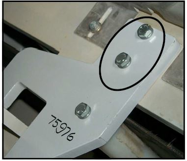
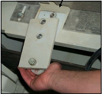
Bearing Block Bolt Replacement
The final step is to replace the bolts which secure the bearings to the arbor mounting plate. There are four bearings blocks on each arbor plate. Use the below photos to locate the bearing block. Both the front and rear arbor assemblies are mechanically build the same components.