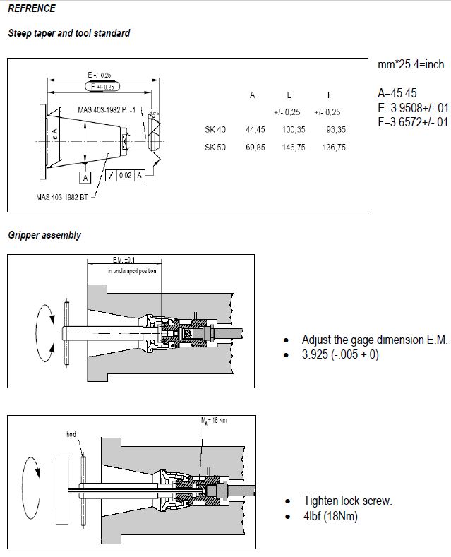
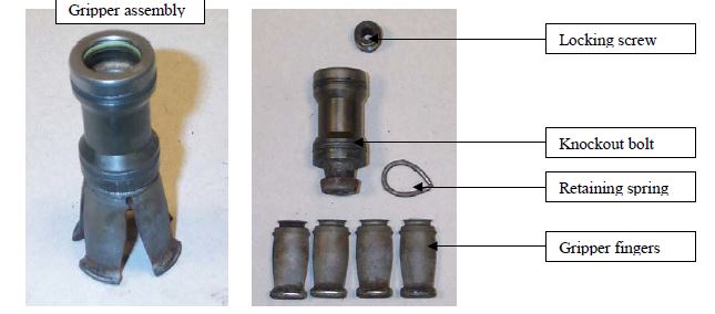
A step by step guide for removal, inspection, cleaning and reinstalling the Weiss Gripper Finger Set
Specialty items used in extraction and insertion of the Clampset (also called Gripset)
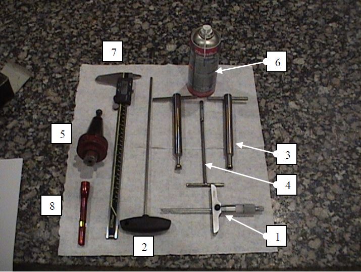
Tools required
1) Depth micrometer 3-4inch, Park Industries# 3094001, Grainger #4KY22
2) 5mm T-handle Allen wrench 8-10inch, Park Industries# 8200374-7
3) Gripper finger adjustment tool, Park Industries# 8200374-8
4) Gripper removal tool, Park Industries#5213007, Threaded rod M8x1.25 10”
5) Tool holder w/ modified retention knob, Park Industries# 60139-S
6) Metaflux grease. Park Industries# 3400037
7) Digital caliper, Park Industries# 8200370
8) Flashlight
9) Shop towels
Removal of the Gripset Assembly
Removal
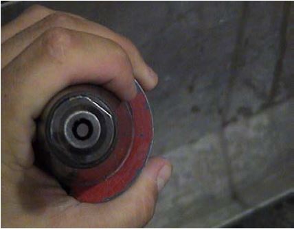
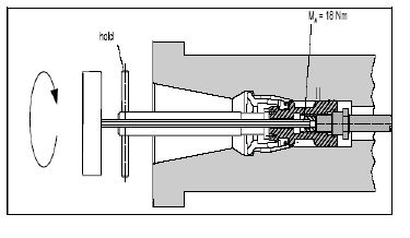
1) Insert tool holder (5) with modified retention knob into the spindle.
2) Use 5mm Allen wrench (2) through the center of tool holder (5), into the spindle. Loosen the locking screw, but do not unscrew it all the way.
3) Press the manual tool release pushbutton and remove the tool holder (5).
4) Insert the gripper finger adjustment tool (3)
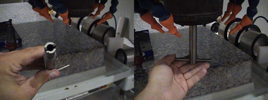
5) unscrew gripper fingers about 8-12 turns, remove adjustment tool (3). Insert removal tool (4) and thread it into the Gripset 3 to five turns. Using a medium amount of force pull the tool (4) downward to remove the Gripset from inside the spindle taper.
Gripset Insertion
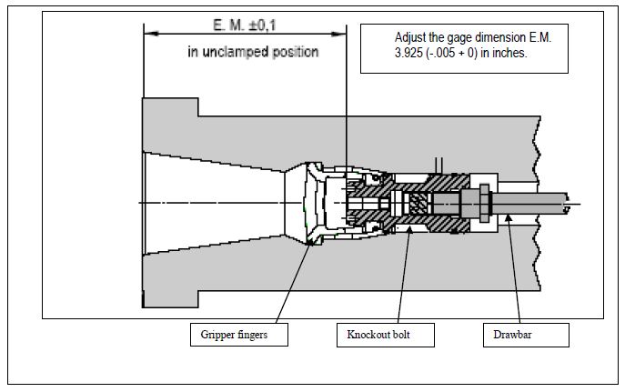
1) Note: Always measure Gripset position in the unclamped position. When the gripper fingers are in the unclamped position you will not be able to turn the spindle. (Manual tool release push button pressed).
2) Screw Removal tool (4) into the body of the Gripset and place Gripset (fingers pointing down) into the spindle taper and remove tool (4).
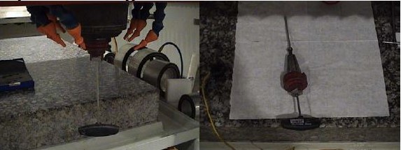
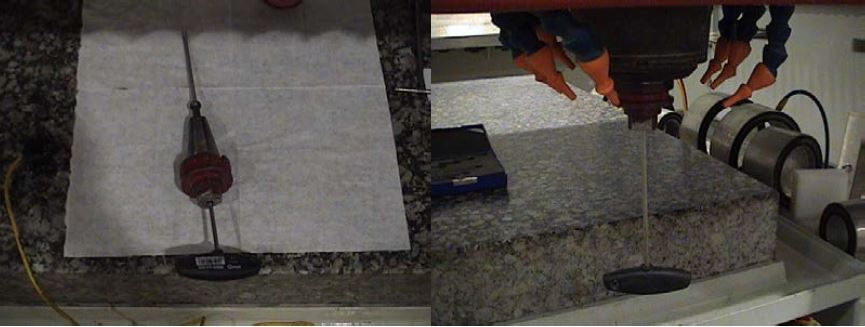
3) Thread Gripset assembly on to the spindle drawbar 8 to 12 turns using tool (4) and measure the dimension with the depth micrometer (1).
If you have MAS style grippers set to 3.925 (-.005 + 0).
If you have a DIN style grippers set to 3.685 ((-.004 + 0).
Place the end of the depth micrometer (1) on the flat visible part of the knockout bolt (use flashlight and visually identify the flat surface to be measured) that is not obstructed by the gripper fingers.
4) When the proper EM dimension is reached, insert 5mm Allen (2) through the center of the adjusting tool (3). Hold the adjusting tool firmly (3) and tighten the locking screw. Do not allow the adjusting tool (3) to turn.
5) measure the EM dimension again. Adjust as needed. Always recheck EM dimension after tightening.
6) Press the manual tool release button and insert the modified tool holder (5) into the spindle, then release the button allowing it to clamp
7) Insert 5mm Allen (2) through the center of the tool holder into the spindle and tighten the locking screw Hand tight. Use care not to overtighten which could lead to stripping the allen wrench flats.
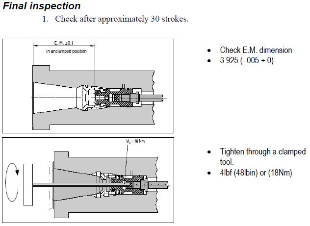
8) hold the tool holder (5) in the spindle and press the manual tool release pushbutton 30 times Retighten the locking screw and recheck dimension
Maintenance, Daily & Weekly
- Daily – Dampen a clean shop towel with Denatured alcohol. Wipe down tool holders, ensure the are clean and dry.
- Weekly – Visually inspect gripper fingers in the spindle with a flashlight. Is it damaged or dirty? Is it sufficiently greased?
- Insert tool with modified retention knob into the spindle. Using a 5mm T-handle Allen wrench, insert it into the center of the tool holder and into the clamp set locking screw. Tighten in a clockwise direction.
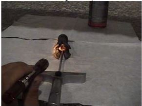
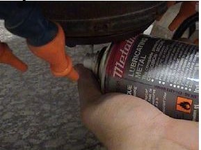
- In the unclamped position (manual tool release pushbutton pressed), using Metaflux grease, spray a 3 second burst of grease onto the gripper fingers.
- Actuated the drawbar with the manual tool release pushbutton 20 times to circulate the grease.
- Wipe excess grease from the taper area where it contacts the too holder.