
Preliminary steps to gain access to the ‘X’ axis bearing for removal and replacement
Scan to Read on Device:

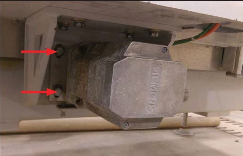
Loosen Motor mount bolts
Remove the x axis servo motor from the machine or lower them out of the gear rack, remove the 4 bolts on each motor.
Loosen these bolts (two
additional on other side)
and lower the gearbox
out of the rack, if your
machine has the gear
box underneath the
machine you may have
to remove the gearbox
from the machine
Remove the ‘X’ axis end Plates & bellows
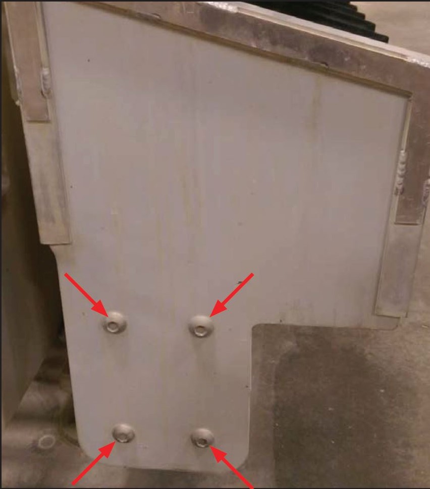
Remove 4 machine bolts to access the rails and bearings.
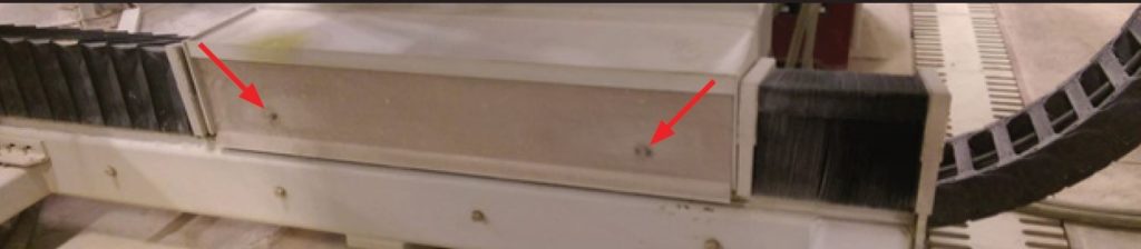
Bearing access cover removal
The bearing bolts are accessible inside the open area as are the grease lines.
Loosen X axis bearing bolts
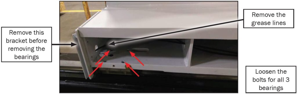
Loosen the bolts. 4 bolts/bearing, 3 bearings per side Disconnect the grease lines but leave them in place for the replacement bearings.
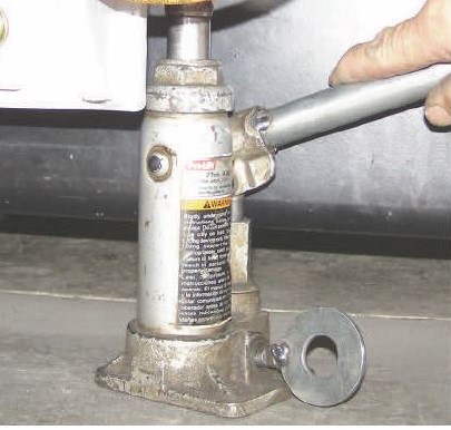
Remove old X axis bearings
Caution: USE WOOD BLOCKING btween the Bridge and the rail for safety. Lift the bridge on one side with a hydraulic bottle Jack no more than 1/32″ OR just enough until you can move the bearings (3 per side). Once the bearings are loose, they can be removed at the Positive end of the X axis rails
Replacing the old bearings
“IMPORTANT” Before installing the new bearings, make sure the orientation on the replacement bearing is exactly the same as the old bearing being removed. If the bearings are installed wrong it will affect the machine accuracy. Note the location of the grease fittings for the grease lines. Also note the location of the bearing DATUM line because it is used to align the bridge to the rails. it is OK to use a thin film of anti-seize on TOP of the bearing before re-assembly.
Repeat the process on the opposite side of the Bridge base
Begin Aligning the Bridge base.
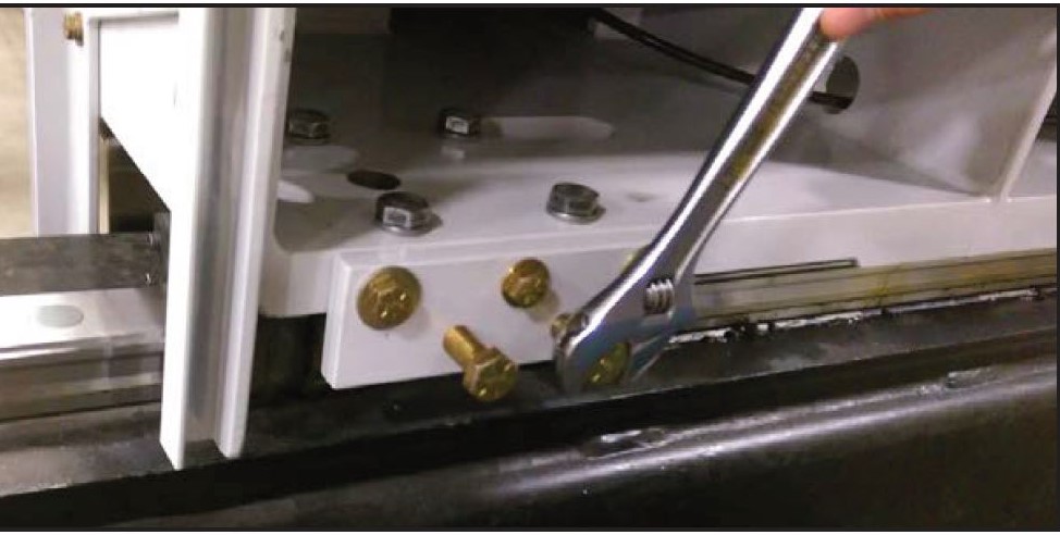
Mount the TW0 plates which are stored inside the openings where the bearings are bolted. Three holes in the plate are used to mount the plate to the bridge base (3/8″). The other two holes are threaded and are used to “Square Up” the bridge to the rails (1/2″). The lower bolts are pushing on the top of the bearing causing the bridge to shift which mates the Datum on the bearing to align with the Datum on the Bridge base.
Aligning the bridge base
Tighten the pusher bolts a little bit initially. Move bridge assembly in the ‘X’ axis by pushing a few feet forward and then backward to help set Bridge base straight on the rails. Tighten squaring bolts snug, then push forward and backward again.. Push the machine back and forth 2-3 times and then tighten all the bolts to 88 ft lbs.
Reinstall the X axis Motors
The motors may now go back to their previous positions. Before repositioning, place a .002″ shim strip on the top of the pinion gear. Keep an eye on the shim as you raise the X motor up to mesh with the gear rack. When the pinion gear is snug with gear rack tighten the 4 mount bolts. More information regarding capturing machine reference here.
Capture new X reference
Turn on Fusion. Navigate to the Advanced Screen and capture the X reference. Shut down the Fusion using proper shut down protocol. When power is disconnected at the main switch, count to 60 and then power up the fusion.
Capture new final X reference
Extreme caution is required when moving the Fusion without limits as it can now reach the hard stops – physical stops. Damage can occur. Restore power to the Fusion. (You may have a prompt that says one or more axis’s are not referenced touch okay and proceed) go to the advanced screen, set the limits to 999 and then move the machine to the front of the machine until the X reference button turns black, slowly turn the machine to the X + at 0.001″ increments until the black box turns green, as soon as it turns green stop and capture the X axis reference proceed to shut down the machine for 2 minutes.
Check limits
Turn the machine back on and return to the advanced setup screen and verify that the x1 and the x2 are at -.050 and that the limits are reading correctly. You have then completed the procedure if you have any questions call customer service (800) 785-3391.