
This use of this guide requires tools to be made in Alphacam under the Machine Tab. If you are unfamiliar with how to create tools in the Machine Tab- such as FLAT END or USER DEFINED TOOLS- please watch our video link below to create additional tooling first.
0:00 Introduction
0:13 Tooling
1:55 Drawing Drain lines
4:18 Locate Part
4:35 Material
5:27 Tool Paths
7:41 Setting the slope
9:24 Tool POS1 second pass
10:18 Tools POS2, 3 and 4
13:03 Copy Tool Path
13:47 Simulation
14:14 Send Code
Programming for this drain board will use tool path Z height edits. The result will be a drain board that slopes in one direction, towards the sink. For a multi direction slope, see the link below called “Programming Multi-Direction Drainboard”.
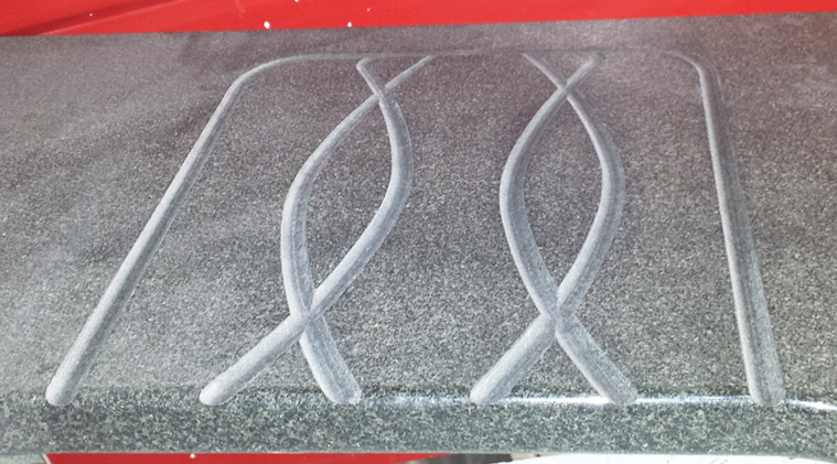
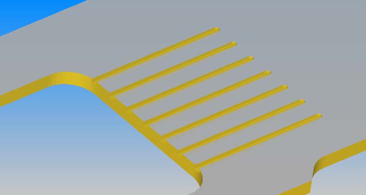
Below is an example of a drain board done with this style of programming. We will program a straight line design which could be used with a variety of tools such as a flat end mill, ball end mill or gauge wheel.
Changing the dimensions and placement of geometry will alter the outcome of your final product. Make adjustments as needed for your desired result.
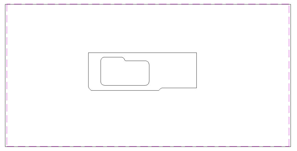
Start with the drawing of your countertop placed on your table template, polished side up.
Draw a line or arc representing the geometry you want to cut.
Place one end of the geometry at the midpoint on the side of the sink. Our example is 12 inches long.
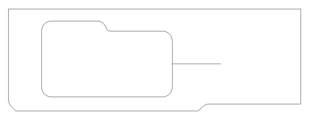
Extend by Distance Command
Use the Extend by Distance command to extend the geometry into the sink, the radius of the tool plus at least one inch. You are creating the “lead in” for the tool. We will be using a ½” diameter tool so we extended the line 1.25”.
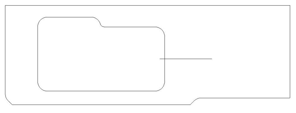
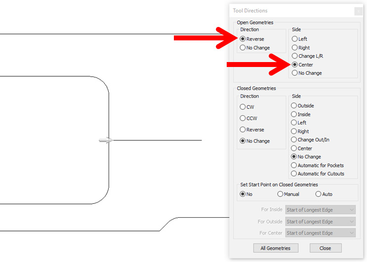
Set the Tool Direction.
Set the Tool Direction for the geometry. Make sure you start inside the sink opening and cut out into the stone and use Center as your Side selection.
Select Tool
Using Select Tool, select the tool you will be using to cut your shape.
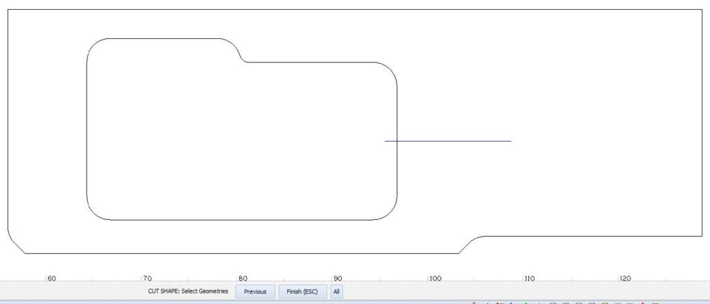
Cut Shape
Select Cut Shape, most of the settings will be the same as a normal cut, however on the Levels and Cuts tab, set the Final Depth to the thickness you want the stone to be in the drain groove at the end furthest from the sink.
Stone thickness – groove depth = Final Depth
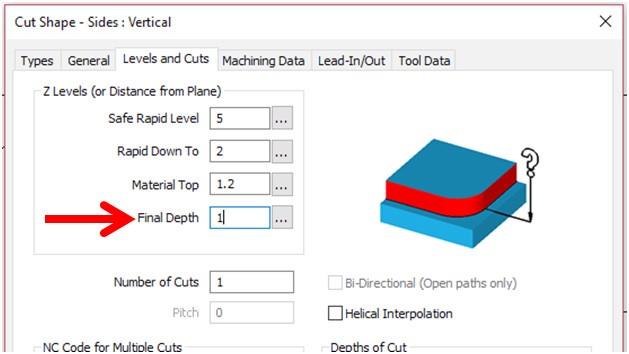
In this example, we are stopping the tool in the stone so there will be a “drop” between the polished surface and the drain board. You can set the height above the stone if you want the tool to exit the stone while cutting for a smooth transition between the polish and the drainboard.
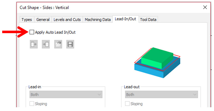
Apply Auto Lead
Also in the Cut Shape pop-up we will make sure the Apply Auto Lead In/Out checkbox on the Lead In/Out tab is unchecked so the toolpaths match the drawn shapes that are selected.
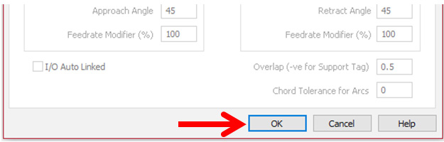
After verifying the settings, click on the pop-up’s OK button.
Select the geometries to toolpath, then Finish.
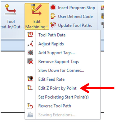
Modify for Desired Slope
We will now modify the toolpath for the desired slope. On the Machine tab, click on the Edit Machining command, then Edit Z Point by Point.
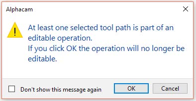
Select the toolpath to edit. If you see the following pop-up, click the OK button.
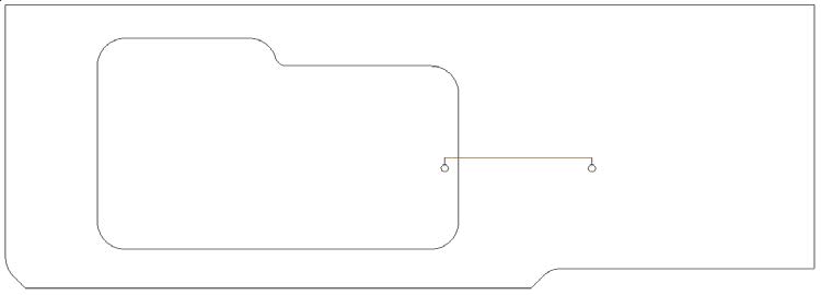
Select Ends of Toolpath
Circles will appear on the ends of your toolpath. Click inside of the circle on the end of the toolpath you want to change the Z height of, this should be the circle inside of your sink.
The height should be less than the Final Depth that was set in step 6.
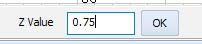
Enter new tool path height
At the bottom of the screen, enter the new height of the toolpath, then click the OK button. In our example we will use .75”.
Note: Depending on material and tool specifications, multiple passes with increasing tool depths may be needed to reach desired final depth. If so, repeat steps 6 through 14. Using the Front view, as shown in step 15, may help you when selecting the desired toolpath when repeating step 9.
Finish Command
Right click or Esc to finish the command. It is not necessary to edit the other end of the toolpath unless you want to change the Final Depth that was set in step 6.
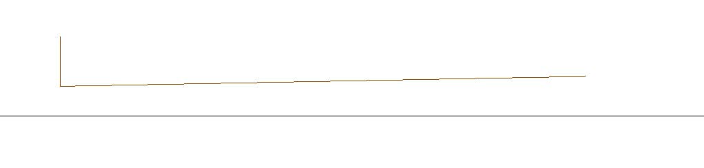
View Side of Toolpath
If you go to the View tab, then select Front, you should see the side view of the toolpath and the slope that will be cut. Notice the tool drop in is on the left side. Press the V key or select Top to return to the normal view.
Repeat Command
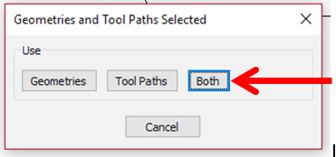
On the Edit tab, select the Repeat command. Select the geometry and toolpath that was just modified.
When the following pop-up appears, select Both.
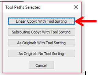
When the following pop-up appears, select Linear Copy: With Tool Sorting
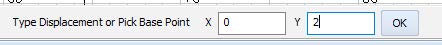
Enter Displacement
At the bottom of the screen, enter the displacement, or amount of the distance between geometries/toolpaths. In our example we will enter 2 in the Y field to place the copies above the original. This is due to the orientation of our piece, sink and toolpaths. Your values may differ.
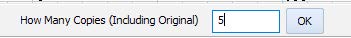
Enter Number of Copies
At the bottom of the screen, enter the number of copies desired including the original. If you create too many copies you can delete the extras. In our example we will enter 5.
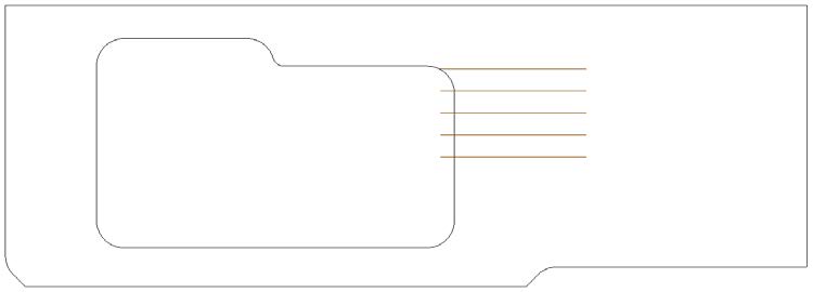
This is the result of the Repeat command:
Repeat steps 16 through 20
Repeat steps 16 through 20 however this time use a negative number when setting the displacement to place the copies below the original. Use the same number that was used in step 20.
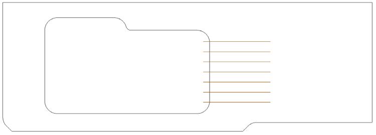
Remove Any Unwanted Paths
Use the Delete command to remove any unwanted geometries/toolpaths. Below is the completed drain board. Notice we deleted one line and toolpath that was created in step 20.
Depending on material and tool specifications, multiple passes may be needed to reach desired depth.
Tags: drainboards boards