
Guide shows how to change the THK bearings on the ‘Y’ axis of the Titan and Destiny.
Scan to Read on Device:

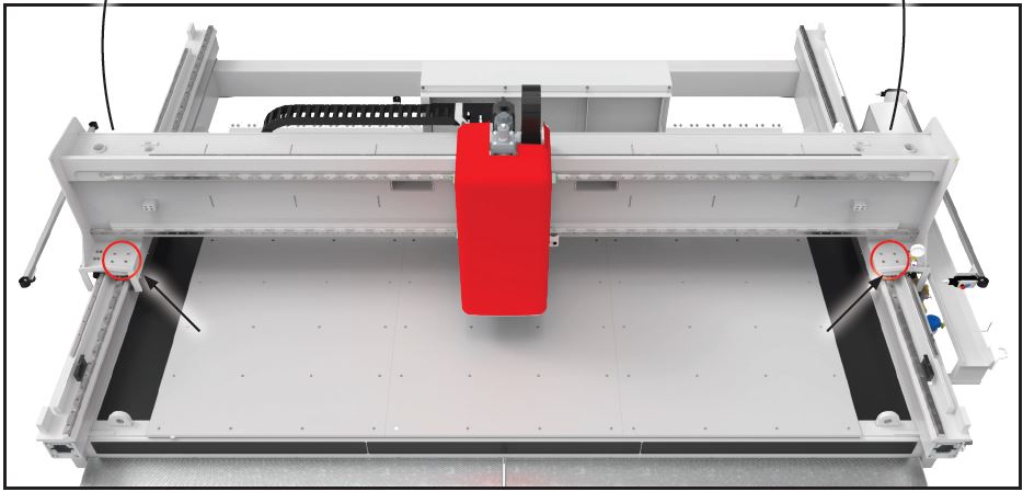
Remove end plates at ends of Y axis on both Y MINUS and Y PLUS ends of the THK RAILS. The old bearings will slide off the exposed ends of the THK rails.
Remove the bellows covers from each THK rail section. The bellows covers are held captive to the THK rails by the bearing grooves and it is easiest to remove the covers by pulling them off each end.
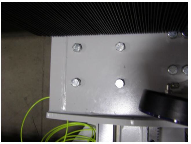
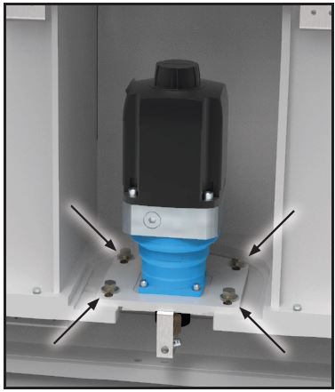
Loosen 4 bolts holding the THK bearing.
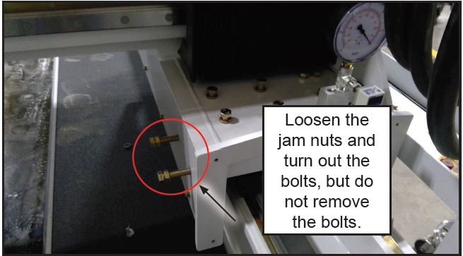
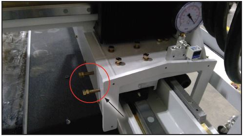
Loosen 4 bolts holding the THK bearing from top side of gantry just above bearing location. There are 4 bolts per bearing (8 per side). Loosen completely but do not remove the bolts from the holes. Also loosen the two pusher bolts and jam nuts on the inside above the table. do not remove.
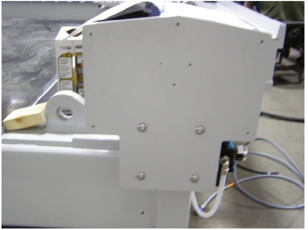
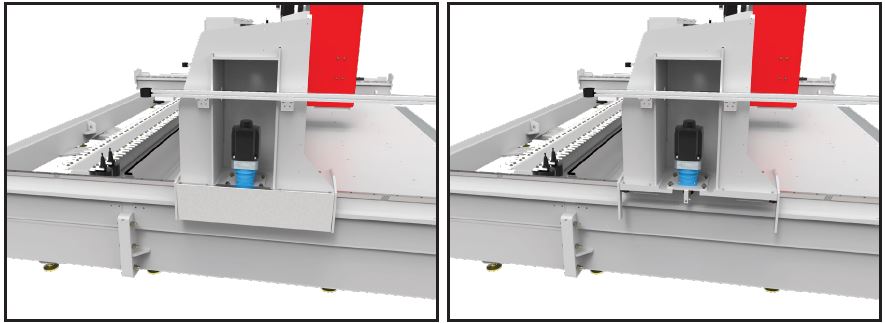
Remove the aluminum covers from each end of the Bridge and loosen the four motor mounting bolts.
Remove the aluminum covers from each end of the Bridge and loosen the four motor mounting bolts. Pull motor assembly away from the center of the machine which separates the pinion gear from the Y gear rack. Repeat opposite side.
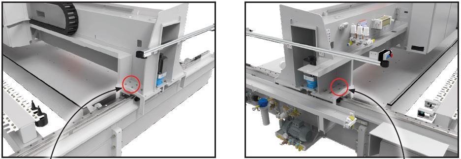
Place a hydraulic jack (5 ton) under gantry in the middle between bearings to be removed.
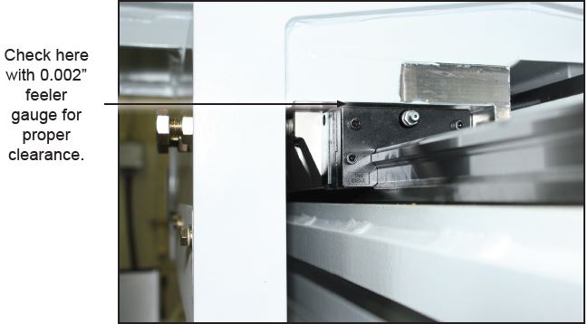
With a dial indicator or a 0.002” feeler gauge jack the gantry to a 0.002” clearance is created between the bearing top side and bottom of gantry where bearing mounts. Slide old bearing OFF the THK rail. Make sure the RAIL is clean before sliding the new replacement.
CAUTION: DO NOT JACK MORE THAN 0.002” UNLESS ALL FOUR BEARINGS HAVE BEEN LOOSENED FROM GANTRY.
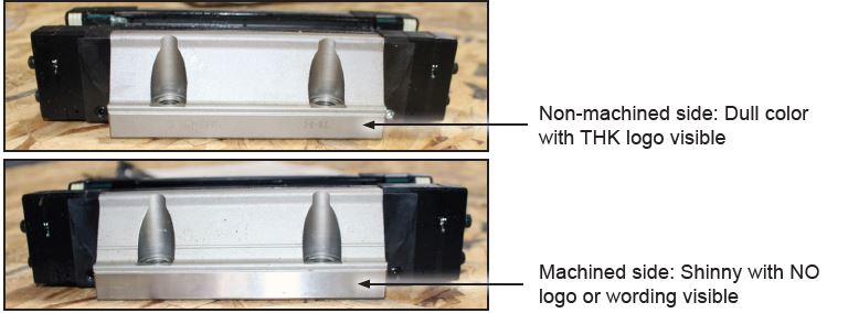
Examine all of the replacement bearings.
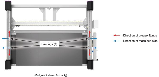
There is a machined and a non-machined side on each bearing. When installing the bearings the machined side MUST face outward from the table and the grease fitting MUST point AWAY from the gantry. If needed you can swap the grease fitting to the other side of the bearing by unscrewing the fitting and the plug from the opposite side of the fitting then reinstall each in the needed location.
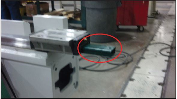
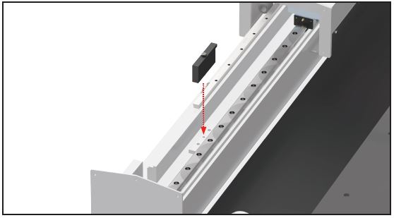
Slide bearing onto the THK rail while holding on to the green plastic protector used to guide the new THK bearing onto rail.
Replace bearings one at a time making sure the shiny machine side is facing out (away from table) and the grease zirk is visible and inline with the Y rail. Tighten all bearing bolts finger tight. The bridge may be pushed from the middle y plus and y minus a few times in order to ‘seat’ the new bearings. The pusher bolts may be finger tight at this point also. Install the squaring blocks
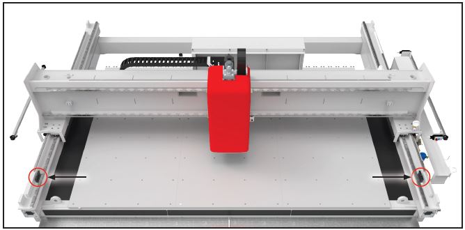
Carefully push the gantry bearing trucks up to the squaring blocks.
The bridge may be pushed up to the Squaring blocks and held in place with clamps. With a 0.002” feeler gauge check clearance at each squaring blocks. There should be no gap. The bearing bolts, pusher bolts and Jam Nuts may all be tightened at this point. Starting with the bearings up against the squaring blocks begin tightening each bolt a half turn at a time going around or across the bearing until it is fully tightened to 70 ft lbs.The squaring blocks are only available on the Titan 2K series. If you have a older model, you can use the hard stops on the machine.
After torquing the bearing bolts, push either Y drive motor pinion gear into the gear rack checking teeth alignment as you push in.
If needed rotate pinion gear so teeth of the pinion and rack are fully meshed when the drive is pushed firmly in. Tighten the 4 bolts.
Repeat steps to engage and tighten “Y” drive motor on the other side of the bridge.
Reinstall bellow covers and ‘End Plates’ at end of each rail.
a. Reference Y axis per web document ‘REFERENCING X AND Y AXES FOR TITAN AND FUSION’ re
ferencing X and y axes for titan and fusion.
Check the backlash for each ‘Y’ motor. Checking backlash – video
b. Perform the spindle referencing procedure omlat spindle replacement & setup OR (found in Operations and Maintenance Manual under Tool Rack Setup).
c. Set the table to spindle height. Use above link OR (found in Operations and Maintenance Manual under Setup).
d. Checking the 0,0 location (refer to Operations and Maintenance Manual under X,Y Dimensions Setup/Table offsets).
e. Check the Overhead Laser offsets (found in Operations and Maintenance Manual under Overhead Laser Calibration).
f. Check all tool pocket locations (found in Operations and Maintenance Manual Tool Rack Setup).